LDU5xxHHC2:
Dual receiver plus 2 x hand-held transmitter and condenser capsule (cardioid), power supply, 2 x BNC antennas, audio cable, 4 x AA
batteries, carrying case, rack kit, instructions
LDU5xxHHD2:
Dual receiver plus 2 x hand-held transmitter and dynamic capsule (cardioid), power supply, 2 x BNC antennas, audio cable, 4 x AA
batteries, carrying case, rack kit, instructions
LDU5xxBPH2:
Dual receiver plus 2 x hand-held transmitter and headset (black), power supply, 2 x BNC antennas, audio cable, 4 x AA batteries, carrying
case, rack kit, instructions
LDU5xxBPHH2:
Dual receiver plus 2 x hand-held transmitter and headset (skin coloured), power supply, 2 x BNC antennas, audio cable, 4 x AA batteries,
carrying case, rack kit, instructions
An extensive selection of suitable LD U500 single components and accessories can be found at www.
LD-SYSTEMS
.COM
CONNECTIONS, CONTROLS AND INDICATORS
1
2
5
3
4
9
8
1
2
3
4
5
6
7
2
3
4
9
8
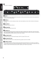
RECEIVER
1
POWER
On / Off switch. Press and hold the switch for approx. 2 seconds to turn the device on or off.
2
DISPLAY
Multi-functional OLED graphics display for displaying information such as radio frequency, radio signal level and audio signal level. Also indicates the
menu items in order to adjust system settings as desired.
3
MENU
Combined pressure rotary encoder to access the Edit menu and to select and edit individual menu items.
4
VOL
Rotary encoder to adjust the audio signal volume of the audio outputs. As soon as volume changes are made, the volume setting will be shown im-
mediately on the display (VOLUME 00 - 100). After approximately 3 seconds of inactivity, the display will automatically return to to the main screen.
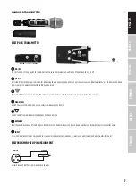
5
Infrared interface for synchronising the relevant system settings of the receiver and the transmitter (e.g. transmission frequency).
6
HEADPHONE OUTPUT
6.3 mm jack socket for connecting a headphone (dual receiver only).
7
HEADPHONE VOLUME LEVEL
Drehregler zum Einstellen der Kopfhörerlautstärke (nur Doppelempfänger).
8
Device for attaching the antennas for rack installation. Remove the covers, attach the BNC adapter to the front panel and connect the BNC antenna
connectors (Fig. 11, dual receiver) to the BNC adapters on the front panel (short antenna cable and BNC adapter included). Now, the antennas can be
attached to the front of the receiver.
5
DEUTSCH
FRANCAIS
ESPAÑOL
ENGLISH
ITALIANO
POLSKI

