6
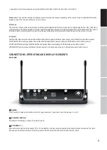
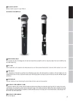
VOL
Rotary knob to adjust the output volume.
IR INTERFACE
Infra-red interface for synchronising the receiver’s radio channel with the transmitter.
ASC
Tosynchronisethetransmitterwiththeradiochannelsetinthereceiver,positiontheinfra-redportofthetransmitterdirectlyinlinewiththe
infra-redinterfaceofthereceiverandswitchonthetransmitterandreceiver(distanceabout10cm,IRinterfaceofthehandtransmitteris
belowthestatusLED,IRinterfaceofthepockettransmitteronthefrontside).NowpresstheASCbuttontostartthesynchronisationprocess.A
redLED indicator will light up in thewindow ofthe IR interfaceduringthe process.Aftera few seconds,the process is completedandoneof the
LED indicators ANTENNA A and B will light up (= wireless connection exists).
LEVEL INDICATOR
5-segment LED chain to display the audio signal level.
ANTENNA A - B
Indicator LEDs for the antenna systems A and B. The antenna system with the stronger radio signal is activated and the corresponding
indicator LED lights up.
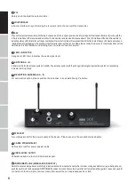
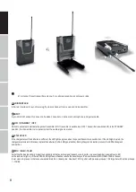
RECEPTION ANTENNAS A - B
For optimum reception, please position the antennas in an upward-facing V-position.
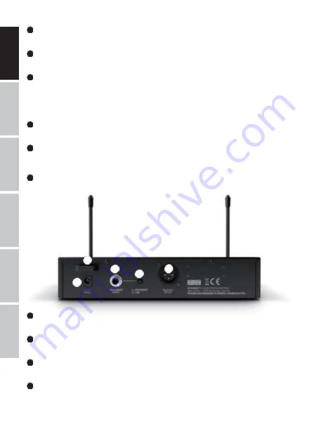
Low-voltage socket for the power supply to the device. Please use only the supplied mains adapter.
11
CABLE STRAIN-RELIEF
Cable strain relief for power adapter cable.
12
UNBALANCED OUTPUT
Unbalanced audio output via 6.3mm jack socket.
13
INSTRUMENT/LINE (UNBALANCED OUTPUT)
Switchforlevelandimpedance-matchingtoinstrumentsorlineinputsofanamplifierormixer.Usingasuitabletool (e.g.aballpointpen),
push the switch into the depressed INSTRUMENT position for connection to the input of an instrument amplifier (guitar or bass amp) and for
connection to the line-input of a mixer or amplifier, select the non-depressed position LINE.
4
5
6
7
8
9
11
12
14
13
10
10
DC SOCKET


