background image

edge - User Manual

Version: 1.0.13/1

Exported on: 22 February, 2024

25

 /  

154


3.6  .edge - Optical Transceivers

To use the network ports on a processing blade, you must fit the correct optical transceivers. These must be Lawo-certified 
and ordered separately from the blade/frame. You will need:

1 x SFP28 - for each 25GbE media port (SFP 1 to 4).
1 x QSFP28 - for each 100GbE media port (QSFP1 & QSFP2).
1 x SFP - for each 1GbE management port (MGMT 1 & 2).

Note that, while it is possible to fit transceivers to all six media ports, only one operating mode can be active: either 

4 x 25G 

(via SFP28)

 or 

2 x 100G (via QSFP28)

.

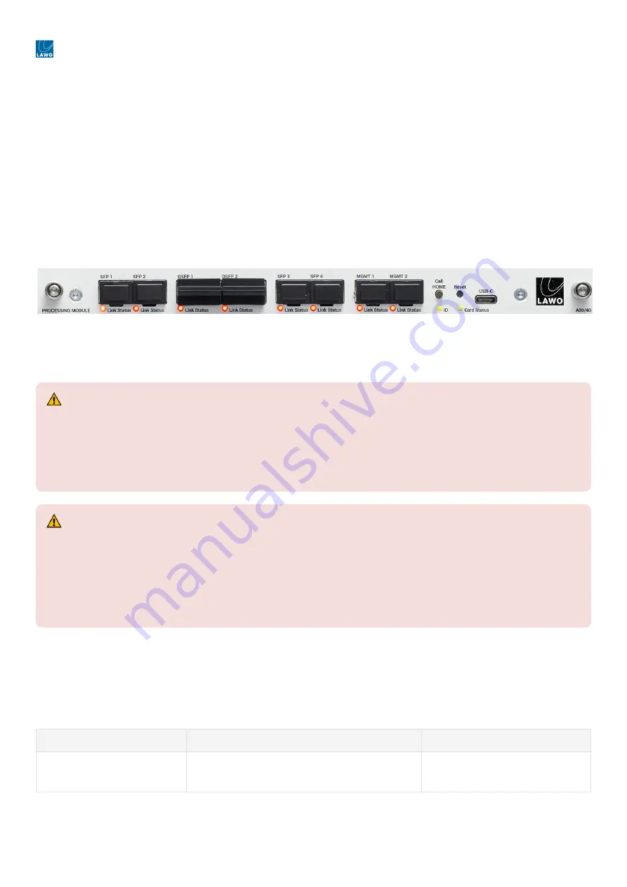
The image below shows the front of a processing blade as it is delivered, with all transceiver cages empty and the dust 
caps fitted.

.edge - Processing Blade (front view)

Lawo-Certified SFP, SFP28 and QSFP28 Modules

The tables below describe the Lawo-certified optical 

transceivers. 

Options for SFP 1 to 4 (25GbE media ports)

Please order 1 x SFP28 for each media port you wish to use. e.g. 4 x SFP28 for redundant 25Gbps operation.

If the processing blade is set to operate at 100Gbps, then these ports are inactive (and the cages can be left empty with 
the dust caps fitted).

Part Number

Description

Notes

.edge_sfp28sr

1 x 25GbE SFP28: short-range (100m) optical 
transceiver.

Up to 4 per blade.


(E) WARNING

If a device has SFP slots, the UL approval of the device is valid only if the used SFP modules are UL-certified and 
comply with the category NWGQ, NWGQ2, AZOT, or AZOT2. The classification of SFPs must be FDA 21 CFR 1010 
or CFR 1040 for products with laser class 1 (I) or IEC 60825-2 for products with LED class 1.
For all other approvals of the device (e.g. CE), the SFP used must have the classification according to IEC 
60825-2 for LED class 1 products.


(F) ATTENTION

Si un appareil possède des emplacements SFP, l'homologation UL de l'appareil n'est valable que si les modules 
SFP utilisés sont certifiés UL et conformes à la catégorie NWGQ, NWGQ2, AZOT ou AZOT2. La classification des 
SFP doit être conforme à la norme FDA 21 CFR 1010 ou CFR 1040 pour les produits avec laser de classe 1 (I) ou 
IEC 60825-2 pour les produits avec LED de classe 1.
Pour toutes les autres homologations de l'appareil (par exemple CE), le SFP utilisé doit avoir la classification 
selon IEC 60825-2 pour les produits à LED de classe 1.

Summary of Contents for edge

Page 1: ...Version 1 0 13 1 Exported on 22 February 2024 To obtain the latest documentation for Lawo products please visit https docs lawo com edge User Manual...

Page 2: ...arks belong to their respective owners It cannot be guaranteed that all product names products trademarks requisitions regulations guidelines specifications and norms are free from trade mark rights o...

Page 3: ...Bundle 36 4 3 Ordering Information 36 5 edge Installation 37 5 1 edge Installation Instructions 38 5 2 edge Unpacking 39 5 3 edge Installing the Frame 40 5 4 edge Fitting the Optical Transceivers 44 5...

Page 4: ...ed Gearbox 128 8 9 edge Advanced SDI Outputs 129 8 10 edge Advanced Statistics 131 8 11 edge Advanced Network Ports 132 8 12 edge Advanced Network Media 134 8 13 edge Advanced Factory 135 8 14 edge Ad...

Page 5: ...edge User Manual Version 1 0 13 1 Exported on 22 February 2024 5 154 This user manual describes all aspects of the edge system It contains information for users technicians and system integrators...

Page 6: ...edge User Manual Version 1 0 13 1 Exported on 22 February 2024 6 154 1 edge General Information Before you start working with edge please read the following information...

Page 7: ...weights and dimensions are available from the Lawo Download Center after login We also recommend that you carefully observe the release notes for your product system Lawo User Registration For access...

Page 8: ...Safety Instructions When working with our hardware components please read and observe all of the instructions provided in the General Safety Information for Lawo Equipment booklet delivered with your...

Page 9: ...ved for treatment with chemical cleaning agents and disinfectants Component surfaces buttons and electronics can be permanently damaged by treatment with such agents and the lifespan can be dramatical...

Page 10: ...13 1 Exported on 22 February 2024 10 154 2 edge Getting Started If you are new to edge then please read the following topics to get started edge Controls Connectors and Indicators edge Operating Prin...

Page 11: ...edge User Manual Version 1 0 13 1 Exported on 22 February 2024 11 154 3 edge Hardware This chapter describes the edge frame and its hardware components...

Page 12: ...cooling fans are included as standard Each processing blade and rear I O plate supports 48 x HD BNC connectors for SDI interfacing The number of available SDIs is license dependent A single frame can...

Page 13: ...later See edge Ordering Information Further Information For dimensions weight power etc see edge Technical Specification and edge Power Supplies For installation information see edge Installing the Fr...

Page 14: ...Supplies 2 x 436 9918 000 black or 436 9919 000 white D1U54P W 1200 12 HC3 series 2 x 436 9914 000 black or 436 9916 000 white PFE1100 12 054RA series Note that the AC power supplies come in a choice...

Page 15: ...blade E WARNING The AC input s MUST be connected to the mains using the power cable s supplied with the system Disconnect all power sources to completely disconnect power from the system e g before yo...

Page 16: ...t overcurrent undervoltage or overvoltage Fan fault or overtemperature Standby overcurrent or undervoltage Internal fault Check the PSU Health pages in HOME s Advanced parameters 2 Amber blinking Powe...

Page 17: ...capacity must fit the requirements of the DC mains power distribution system The wires that feed the DC PSU must offer a cable cross section at least of AWG 10 5 2 mm Please check whether a higher cab...

Page 18: ...n lock marking and cable tie Once the installation is complete the frame should be powered on and off using the disconnect device The PSU status can be checked using the two LEDs at the front describe...

Page 19: ...tions in the General Safety Information for Lawo Equipment booklet delivered with your devices Use the M5x12 screw to fasten the grounding cable to the housing You should use a Torx T25 driver for thi...

Page 20: ...all frame variants To order a spare part use the part number A00 10 55 The fan tray is removable and can be exchanged from the front of the frame See Replacing the Fan Tray for instructions E ATTENTIO...

Page 21: ...edge User Manual Version 1 0 13 1 Exported on 22 February 2024 21 154 Further Information For permitted operating and storage temperatures see edge Technical Specification...

Page 22: ...cally the highest blade is always the master e g slot 1 in a fully populated frame The master blade determines the fan activity and error reporting Internal Components Internally each processing blade...

Page 23: ...GMT ports 2 x 1GbE via SFP This scheme requires a dedicated management network To achieve redundant control you must use both interfaces In band control data arrives via the media ports This scheme ca...

Page 24: ...s from a service computer Card Status LED shows the health of the processing blade and chassis on the master blade For more information see edge Controls Connectors and Indicators Ordering Information...

Page 25: ...is set to operate at 100Gbps then these ports are inactive and the cages can be left empty with the dust caps fitted Part Number Description Notes edge_sfp28sr 1 x 25GbE SFP28 short range 100m optical...

Page 26: ...qsfp28lr 1 x 100GbE QSFP28 long range 10km optical transceiver Up to 2 per blade Options for MGMT 1 2 1GbE management ports Please order 1 x SFP for each management port you wish to use e g 2 x SFP fo...

Page 27: ...interfaces This can be expanded by adding either one or two edge_sdi licenses to enable 32 or 48 SDI interfaces Thus there are three licensing options for each blade Base system 1 x edge_sdi_inc lice...

Page 28: ...the block unused Or if using 3G UHD gearboxing connect the 4 x 3G SDI signals to a quad link block 1 4 5 8 9 12 etc This option requires a edge_gbox license for each quad link instance In both cases i...

Page 29: ...ooped through output of the corresponding IN The REF OUT is always active and provides an output of the current reference External IN 1 External IN 2 PTP or Internal free run The current reference can...

Page 30: ...Manual Version 1 0 13 1 Exported on 22 February 2024 30 154 Specifications For information about the SDI and reference standards supported formats return loss and cable lengths see edge Technical Spec...

Page 31: ...e rear I O plate and 1 x SDI license To order a replacement part see spare parts edge Part Number Description Notes Frame Variants edge_frame ac rails1 edge frame fitted with 2 x AC power supplies 1 x...

Page 32: ...o 4 per blade fitted to SFP ports edge_sfp28lr 1 x 25GbE SFP28 long range 10km optical transceiver edge_qsfp28sr 1 x 100GbE QSFP28 short range 100m optical transceiver Up to 2 per blade fitted to QSFP...

Page 33: ...The number of crosspoints is specified for SD and HD operation at 25G Each bundle is a complete multi frame system with a HOME server cluster The HOME cluster license supports up to 50 devices Spare P...

Page 34: ...2 1 x edge frame rack mounting kit with 600mm rails edge_frame rails1 1 x edge frame rack mounting kit with 800 900mm rails edge_frame hdbnc1 1 x HD BNC removal tool 1 TG edge_frame hdbnc2 1 x HD BNC...

Page 35: ...x SDI interfaces on the rear I O plate Each edge_gateway processing blade comes with a single edge_sdi_inc license for 16 x SDIs The number of SDIs can be expanded by adding one or two edge_sdi licen...

Page 36: ...2G signal 100G Operation The edge_100g software license enables the 2 x 100GbE option for the media network interfaces It allows the processing blade to operate at 100Gbps and enables support of 3G an...

Page 37: ...edge User Manual Version 1 0 13 1 Exported on 22 February 2024 37 154 5 edge Installation This chapter describes how to install the edge hardware...

Page 38: ...ng order Unpack Fit the Processing Blades and Rear I O Plates Install the Frame Fit the Optical Transceivers Cable the system Check the synchronization The rest of this chapter describes each task in...

Page 39: ...o the equipment rack 2 x IEC power cables country specific to connect mains to the AC power supplies 4 x front slot blanking panels to close the slots at the front of the frame 4 x rear slot blanking...

Page 40: ...the front grill Air is taken in from the front and blown out across the processing blades to the right The image below shows the direction of airflow E ATTENTION DO NOT obstruct the ventilation holes...

Page 41: ...NG Please read and observe ALL of the Important Safety Instructions BEFORE installing the frame F AVERTISSEMENT Veuillez lire et respecter TOUTES les consignes de s curit importantes AVANT d installer...

Page 42: ...800 900mm pdf Each kit contains 2 x rack mounting brackets rails with ears to span the gap between the rack and frame 6 x screws M3x4 to secure the brackets to the frame Using the screws provided fix...

Page 43: ...edge User Manual Version 1 0 13 1 Exported on 22 February 2024 43 154...

Page 44: ...ts or optical fibre cables Keep optical components closed by protection plugs when unused For your safety connect all fibre cables first before turning on the equipment F ATTENTION Cet quipement peut...

Page 45: ...ithout lifting the extraction lever If the module cannot be removed it is installed correctly If the module can be removed then check its orientation perhaps the SFP is inserted upside down Repeat ste...

Page 46: ...ing blade is set to operate at 25G If a valid 100G license is available then a blade can be set to operate at either 25G or 100G For each stream you can decide whether it will be transmitted or receiv...

Page 47: ...tes 5 Reference Interfaces 5 x HD BNC For external synchronization there are 5 x HD BNC connectors 2 x REF IN 2 x REF THRU and 1 x REF OUT The two reference inputs can be used to connect up to two ext...

Page 48: ...the Synchronization options in HOME s Advanced parameters From the main Devices list click on the processing blade label to open the Device Details as described earlier Then select the Advanced tab an...

Page 49: ...lock signal is detected then the PTP field will show Locked Using an External Reference If PTP is not available or you wish to connect a backup sync pulse generator then you can connect up to two exte...

Page 50: ...e g from an external grandmaster If Slave Only is disabled then the processing blade will operate as either a master or slave depending on the PTP priorities set within the device itself and the other...

Page 51: ...parameters in turn Priority 1 the lower the number the higher the priority of the device Clock Class Priority 2 as for Priority 1 MAC Address For example if there is no Priority 1 available then all d...

Page 52: ...Port PTP The Enable Port PTP options can be used to define which ports are listening for PTP from the media network or transmitting PTP if the blade is running as master The available ports depend on...

Page 53: ...chapter describes how to set up the system once all of the hardware components are installed edge Setup Checklist edge NATS Server IP or Hostname edge Network Settings edge Device Information edge Li...

Page 54: ...hat the processing blade appears in HOME s Devices list The Devices list shows all devices known to HOME If this is a first time connection then you will need to Approve the device before you can cont...

Page 55: ...lternatively the NATS Server IP Hostname parameter can be modified to match the existing DNS Server although this would need to be modified in the HOME configuration also The NATS Server IP Hostname p...

Page 56: ...edia ports If you wish to reset the network settings for all ports management and media then this can be achieved using the Factory Reset Network Settings option in HOME s Advanced parameters Control...

Page 57: ...ists all of the active network ports Device Network Ports From here you can quickly check the status of all network ports or edit the IP settings of a port as shown below The table shows information a...

Page 58: ...edge User Manual Version 1 0 13 1 Exported on 22 February 2024 58 154...

Page 59: ...Device Details as described earlier The page opens with the General tab selected The General tab is divided into two sections with general information about the processing blade on the left and other...

Page 60: ...o or from a particular device in the Stream Routing Entering a location is optional Identifying a Processing Blade The Identify Hardware button can be used to identify the hardware in the equipment ra...

Page 61: ...de the ID LED repeatedly changes color from red to blue To cancel the Identify Hardware mode either deselect Identify Hardware on the GUI or press and hold the Call Home button again on the unit Other...

Page 62: ...e All software licenses are perpetual and locked to an individual processing blade using the Serial Number provided by the customer Licenses cannot be transferred between blades If a blade fails and y...

Page 63: ...is selected click on the Upload button to start the transfer Following a successful upload the file is added to the Licenses list How the Licenses folder will look after a successful upload Each lic f...

Page 64: ...how they are assigned using the License Configuration page in HOME s Advanced parameters License Configuration main page From the main page you can configure the operating mode and SDI interfacing The...

Page 65: ...onfiguration So to change the number of SDIs the complete workflow is as follows Edit the Additional SDI parameter Push the change to the processing blade click on TAKE Configuration Changes Trigger E...

Page 66: ...e Input Synchronization Assignment sub page you can assign the input frame sync licenses to the SDI inputs License Configuration Input Synchronization Assignment Firstly there are two informational fi...

Page 67: ...edge User Manual Version 1 0 13 1 Exported on 22 February 2024 67 154 Once the processing blade comes back online the new license assignments can be easily checked from HOME s SDI I O tab...

Page 68: ...ation The edge_100g software license enables the 2 x 100GbE option for the media network interfaces It allows the processing blade to operate at 100Gbps and enables support of 3G and 12G format signal...

Page 69: ...Gateway 100G Note that if a 100G license is not available then only one option is possible 25G For security you must enter the confirmation text and then click Apply The processing blade goes offline...

Page 70: ...processing blade comes with a single edge_sdi_inc license for 16 x SDIs The number of SDIs can be expanded by adding one or two edge_sdi licenses for 32 or 48 x SDIs Licensing Requirements 1 x edge_s...

Page 71: ...described earlier Click on the Edit button under Device Options Choose one of the three options from the drop down menu For security you must enter the confirmation text and then click Apply The proc...

Page 72: ...address manually The first option is the simplest as it offers complete automation The second two options can be used if you need more manual control e g to fit an existing multicast scheme The tables...

Page 73: ...This means that 40 is used for audio block 1 from SDI 1 41 audio block 2 from SDI 1 etc Configuration via HOME For options 1 and 2 the mode of assignment and starting IP values are defined using the...

Page 74: ...e primary network and those in blue are pushed to the secondary network If you need to check the source IPs then this can be done from the Network Ports tab The screenshots below show the steps Option...

Page 75: ...the individual IP Senders for each SDI input Open the SDI Inputs branch of the Advanced parameters Open SDI 01 IP Senders and Video Type in the multicast addresses into the IP Primary Multicast and I...

Page 76: ...ld and then use the corresponding Trigger Event button to push the values to the IP senders Checking the IP Senders All of the settings above can be checked from the Senders tab as follows From the ma...

Page 77: ...to operate the system once the initial setup is complete edge Controls Connectors and Indicators edge Operating Principles edge IP Senders and Receivers edge SDI Inputs and Outputs edge Stream Routing...

Page 78: ...own Each power supply has two status LEDs that can be used to check the health of the PSU LED 1 power lights in green when the power is ok LED 2 fault lights in amber if there is a fault or warning Th...

Page 79: ...or 2 x 100GbE via QSFP28 The MGMT ports connect the processing blade to the management network s 2 x 1GbE via SFP Each network port has a Link Status LED that can be used to check the Ethernet connect...

Page 80: ...he connection should be made using a standard USB Type C cable 7 Card Status The Card Status LED shows the health of the processing blade and chassis The LED has three possible states green amber or r...

Page 81: ...xternal reference signals 2 x REF IN 2 x REF THRU and 1 x REF OUT The sync reference can be checked or changed using the Synchronization parameters in HOME s Advanced parameters 10 Grounding Screw A g...

Page 82: ...y by HOME s DHCP server To control a processing blade using HOME you will need a computer that is installed with a suitable web browser application to open the HOME Web UI The computer must be connect...

Page 83: ...g each processing blade then you can use the Identify Hardware function The label and location of each processing blade can be edited using the Edit Device Info function Adjusting Settings All of the...

Page 84: ...Routing for the audio streams edit the streaming parameters or access the SDP data In addition the Show Sidebar button on the right reveals the available properties for the selected sender or receive...

Page 85: ...or is disconnected then any streaming connections to and from the device are lost However the connections are still prepared This means that as soon as the device comes back online its streaming conne...

Page 86: ...ut parameters on the SDI side Here we deal with the former For more information on the latter see edge SDI Inputs and Outputs IP Senders and Receivers The Senders and Receivers tabs list all of the pr...

Page 87: ...edge User Manual Version 1 0 13 1 Exported on 22 February 2024 87 154 IP Senders audio sender properties...

Page 88: ...he status of the stream Hover over the icon to reveal more information Stream Information shows a summary of the stream parameters e g for a video stream the IP standard and video format for an audio...

Page 89: ...therwise known as audio shuffling Parameters check or edit the stream parameters SDP Data view or copy paste the stream s SDP IP Receivers The Receivers tab works in a similar manner but this tab list...

Page 90: ...edge User Manual Version 1 0 13 1 Exported on 22 February 2024 90 154 IP Receivers audio receiver properties...

Page 91: ...e shows the name of the network interface s used by the receiver Status indicates the status of the receiver Hover over the icon to reveal more information Connected Source shows the name of the conne...

Page 92: ...ions If you select a receiver then a number of other functions become available I O Routing for audio receivers only assigns the IP receiver channels to the SDI audio outputs Otherwise known as audio...

Page 93: ...the ident and test pattern or adjust the gearboxing and input frame sync if the relevant licenses are active From the main Devices list click on the processing blade label to open the Device Details...

Page 94: ...license SDI Input Mode shows the mode of the SDI input Gearbox turns the video gearbox on or off Note that the option is hidden if there is no gearbox license There are three possible modes Auto On a...

Page 95: ...a warning triangle in this column 3G to 12G Gearbox shows On if video gearboxing is enabled SDI Output Properties The following properties can be adjusted by selecting an SDI output and revealing the...

Page 96: ...led Delay adjusts the video delay up to 6 frames OR fields depending on the video standard Ident turns the video ident on or off When the option is turned on the Ident text appears on the SDI output C...

Page 97: ...nd so the same steps apply to all devices known to HOME For edge the main points are The senders and receivers are pre defined where each one handles the three essence types of an SDI I O 1 x Video 4...

Page 98: ...edge User Manual Version 1 0 13 1 Exported on 22 February 2024 98 154...

Page 99: ...ent mono audio channel mapping per SDI output selectable number of channels up to 64 Test tone generator insertion 400Hz to 1kHz frequency control with decreasing ramp 0 5dB per channel The examples t...

Page 100: ...eceiving side each IP receiver can handle 64 audio channels as before For the final audio packaging any of the 64 channels sent to the four IP receivers can be shuffled into the final 32 audio channel...

Page 101: ...udio channels and can output 32 of them Thus edge supports a combined 128 audio channels 4 x 32 ch as defined for the 12G Quad Link standard IP to SDI Conversion for 4 x 3G SDI UHD 2160p 1 x 12G SDI S...

Page 102: ...embedding or the Receivers tab to configure the embedding Select the audio sender or receiver you wish to adjust and select the I O Routing button The I O Routing page is used to connect the IP channe...

Page 103: ...edge User Manual Version 1 0 13 1 Exported on 22 February 2024 103 154...

Page 104: ...the delay of the picture content increases or decreases by a frame The timing of the start of the SDI frame will vary directly with the horizontal and vertical offsets but the delay of the content is...

Page 105: ...sidebar to access the SDI input parameters For an SDI input turn on the Frame Synchronizer slider Then use the and buttons to adjust the Pixel and Line Offsets For an SDI output the frame synchronize...

Page 106: ...tion Includes VPID insertion on the output interface 2 sample interleave SMPTE ST352 payload identification Link Rotate allows automatic reshuffling of a four wire 3G SDI link whose cables were connec...

Page 107: ...SDI Inputs Preset Alternatively you can choose to force the option on or off When the Gearbox is active the Link Rotate option can be enabled to fix any errors in the input cabling Troubleshooting If...

Page 108: ...eceiver Configuration via HOME Video Delay In HOME there are two ways to access the video delay parameters via the SDI I O tab or Advanced parameters Video Delay for SDI Output From the main Devices l...

Page 109: ...lay is added to the IP receiver so switch to the Receivers tab to access the option In this instance the delay can be adjusted in either ms or samples Audio Delay for IP Receiver The same features can...

Page 110: ...Bars for SDI Outputs Thus the direction can be used to determine where the test pattern is enabled on the input or output Video Ident When enabled the video ident text is displayed on the selected in...

Page 111: ...edge User Manual Version 1 0 13 1 Exported on 22 February 2024 111 154 The test tone for an audio input is adjusted from the Senders tab Audio Test Tone for audio sender...

Page 112: ...edge User Manual Version 1 0 13 1 Exported on 22 February 2024 112 154 The test tone for an audio output is adjusted from the Senders tab for the selected SDI output Audio Test Tone for audio output...

Page 113: ...edge User Manual Version 1 0 13 1 Exported on 22 February 2024 113 154...

Page 114: ...rol from HOME edge Advanced Identity edge Advanced System controls edge Advanced Health edge Advanced Synchronization edge Advanced SDI Inputs edge Advanced IP Sender Multicast edge Advanced Gearbox e...

Page 115: ...edge Advanced Identity edge Advanced System controls edge Advanced Health edge Advanced Synchronization edge Advanced SDI Inputs edge Advanced IP Sender Multicast edge Advanced Gearbox edge Advanced...

Page 116: ...e the next level Or scroll down to the bottom of the parameter area to view the Sub Pages as a list The example below shows how to navigate to the Synchronization PTP page If a field can be edited the...

Page 117: ...the Role Name and Location of the processing blade The remaining fields are for information only Available Parameters The table below describes all available parameters Advanced tree path Parameter Po...

Page 118: ...Read only Describes the serial number important for licensing NATS ID Read only GUID Read only Mode Read only FPGA Version Read only Describes the build version of the FPGA FPGA Build Time Read only S...

Page 119: ...all available parameters Advanced tree path Parameter Possible Values Further Information System controls Chassis Fault s Read only The first four fields show information about any chassis and card f...

Page 120: ...sing blade since the last restart reboot IGMP V3 SSM Enabled Disabled IGMP Use UDP Dest Port Enabled Disabled Rest API Enable Enabled Disabled Rest API Port Numerical entry NATS Server IP Hostname Tex...

Page 121: ...tage and current Operation using HOME There is a separate sub page for each component The screenshots below show the Health pages for a PSU and the fans Health PSUs PSU 1 Health Fan Status Other pages...

Page 122: ...the Set Point and the Current Temp Value providing that the Enable Temperature Updates option is enabled under All Temperature Monitoring If the Current Temp Value exceed the Set Point then the fan sp...

Page 123: ...e parameters Advanced tree path Parameter Possible Values Further Information Synchronization Status Summary Read only Shows Locked when the processing blade is locked i e the Mode Select field e g PT...

Page 124: ...rmation Ext Reference Format Read only If the Mode Select field is set to one of the external inputs then this field shows the format of the incoming signal Reference Output Format Various Defines the...

Page 125: ...each individual channel A better overview can be obtained from the Audio signal present LEDs on the SDI I O tab Frame Synchronizer see edge Frame Synchronization SMPTE 352 Ident see edge Test Signals...

Page 126: ...edge User Manual Version 1 0 13 1 Exported on 22 February 2024 126 154...

Page 127: ...er Multicast page can be used to automatically define the multicast IP addresses for the IP senders Please see edge Multicast IP Addresses for more information Operation using HOME All parameters are...

Page 128: ...or each input and output instance Note that the instances are determined by the gearbox license assignments So if you cannot see a Gearbox option for the required input or output you will need to modi...

Page 129: ...elow for more information Audio Embedders Frame Synchronizer see edge Frame Synchronization Test Pattern see edge Test Signals Ident see edge Test Signals Audio Tone Generator see edge Test Signals IP...

Page 130: ...edge User Manual Version 1 0 13 1 Exported on 22 February 2024 130 154...

Page 131: ...ngle string per SDI IP Senders individual statistics per IP sender video audio and meta IP Receivers individual statistics per IP receiver video audio and meta Multicast IP Rx statistics for the multi...

Page 132: ...that may be useful to a network administrator Of particular note are PING test click on Trigger Event to run a PING test to the HOME server The results are displayed in the PING Output field SFP Info...

Page 133: ...ossible Values Further Information Enable DHCP Active Off Choose Off to configure a static IP IP Address current Read only IP Address fixed CIDR Enter IP Used if Enable DHCP is set to Off Static Defau...

Page 134: ...the multicast IPs of the media ports Operation using HOME Open the Network Media branch and select a port e g QSFP 1 There is one sub page for each active port Network Media Port The Multicast sub pag...

Page 135: ...E All parameters are displayed on a single page Factory There are two parameters available Reset All Settings except Network this field resets all parameters except for the network settings defined in...

Page 136: ...e manages all of the software licenses Please see edge License Activation for more information Operation using HOME From the main page you can configure the operating mode and SDI interfacing There ar...

Page 137: ...etwork It is supported by a wide range of products and manufacturers More details about the Ember protocol can be found at https github com Lawo ember plus wiki To access edge parameters via Ember you...

Page 138: ...describes how to control a processing blade via REST API Overview REST API is a scripting protocol that allows devices to be remotely controlled via the network Scripting A script can address the sam...

Page 139: ...4 9 edge Service Procedures This chapter describes the service procedures available for the edge hardware edge Using the Service Procedures edge Replacing a Power Supply Unit edge Replacing the Fan Tr...

Page 140: ...login The following procedures are covered in this chapter Replacing a Power Supply Unit Replacing the Fan Tray Replacing a Processing Blade Replacing a Rear I O Plate If you need further assistance...

Page 141: ...Each edge frame is powered by two power supplies fitted to the front Only one PSU is required for operation the second provides redundancy The power supplies are hot pluggable and so it is possible to...

Page 142: ...Reconnect the power source and test the operation of the PSUs For AC power supplies reconnect the IEC mains cable For DC power supplies replace the DC feeding wires and cable strain relief Then turn o...

Page 143: ...t grill There are three large fans to cool the processing blades plus two smaller fans to cool the rear I O plates If a fan is faulty you can replace the complete fan tray from the front of the frame...

Page 144: ...ld be tightened alternately so that the fan tray fits smoothly into the frame If you tighten one screw completely then you may cause damage to the fan tray or frame 4 Reconnect the IEC power cables an...

Page 145: ...lades are hot pluggable and so it is possible to add or replace a blade while the frame is powered What you will need 1 x Torx10 driver included in the Lawo toolkit supplied with the system 1 x edge p...

Page 146: ...alternately so that the blade fits smoothly into the frame If you tighten one screw completely then you may cause damage to the blade or frame A blanking panel can be fitted in a similar manner Each p...

Page 147: ...it is possible to add or replace a plate while the frame is powered What you will need 1 x Torx10 driver included in the Lawo toolkit supplied with the system 1 x HD BNC removal tool included in the...

Page 148: ...rame Secure by tightening the 2 x Torx10 screws The screws should be tightened alternately so that the I O plate fits smoothly into the frame If you tighten one screw completely then you may cause dam...

Page 149: ...1 Exported on 22 February 2024 149 154 10 edge Data and Specifications This chapter contains data to work with such as specifications and release information edge Type Numbers edge Technical Specific...

Page 150: ...mechanical drawings and data sheets can be located using the following type numbers A00 10 edge frame with AC supplies A00 20 edge frame with DC supplies A00 40 edge processing blade A00 50 edge rear...

Page 151: ...Cable Length Reference Connectors edge Frame Dimensions Height x Width x Depth 88 1 mm 2RU x 483 mm 19 x 412 mm Depth measured without excess length screws handles Weight Frame with fan tray fitted 5...

Page 152: ...ompressed Active Video ST2110 21 Traffic Shaping and Delivery Timing for Video ST2110 30 PCM Digital Audio Levels A B and C ST2110 31 AES3 Transparent Transport Levels A B and C ST2110 40 SMPTE ST291...

Page 153: ...xed 24 bi directional software defined SDI Standards SD SMPTE ST259M C 270Mb s HD SMPTE ST292 1 485 1 485 1 001 Gb s 3G SMPTE ST424 2 970 2 970 1 001 Gb s 12G SMPTE ST2082 1 2015 Supported Formats SD...

Page 154: ...DF ADD LINK edge integrates natively with HOME edge supports the following interface solutions Alliance for IP Media Solutions AIMS RAVENNA Ember REST API Q How do I check the software versions runnin...

Reviews: