


Lawn Boy, Inc. - 1999
All Rights Reserved
Printed in USA
2
Contents
Page
Introduction
2
. . . . . . . . . . . . . . . . . . . . . . . . . . . . . . . . .
Safety
3
. . . . . . . . . . . . . . . . . . . . . . . . . . . . . . . . . . . . . .
General Snowthrower Safety
3
. . . . . . . . . . . . . . . . .
Lawn-Boy Snowthrower Safety
4
. . . . . . . . . . . . . . .
Safety Decals and Instructions
5
. . . . . . . . . . . . . . . .
Loose Parts
6
. . . . . . . . . . . . . . . . . . . . . . . . . . . . . . . . . .
Accessories
7
. . . . . . . . . . . . . . . . . . . . . . . . . . . . . . . . .
Assembly
7
. . . . . . . . . . . . . . . . . . . . . . . . . . . . . . . . . . .
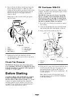
Install Handle
7
. . . . . . . . . . . . . . . . . . . . . . . . . . . . .
Install Speed Selector Rod
8
. . . . . . . . . . . . . . . . . . .
Install Traction Rod
8
. . . . . . . . . . . . . . . . . . . . . . . .
Install Auger Drive Control Linkage
8
. . . . . . . . . . .
Install Chute Control Rod
9
. . . . . . . . . . . . . . . . . . .
Secure Chute Deflector
9
. . . . . . . . . . . . . . . . . . . . .
Check Tire Pressure
10
. . . . . . . . . . . . . . . . . . . . . . . .
Before Starting
10
. . . . . . . . . . . . . . . . . . . . . . . . . . . . . . .
Fill Crankcase With Oil
10
. . . . . . . . . . . . . . . . . . . . .
Fill Fuel Tank With Gasoline
11
. . . . . . . . . . . . . . . . .
Operation
11
. . . . . . . . . . . . . . . . . . . . . . . . . . . . . . . . . . .
Controls
11
. . . . . . . . . . . . . . . . . . . . . . . . . . . . . . . . .
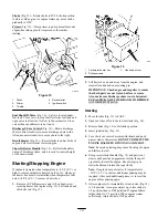
Starting/Stopping Engine
12
. . . . . . . . . . . . . . . . . . . .
Operating Tips
13
. . . . . . . . . . . . . . . . . . . . . . . . . . . .
Adjusting Skids And Scraper Blade
13
. . . . . . . . . . . .
Maintenance
14
. . . . . . . . . . . . . . . . . . . . . . . . . . . . . . . . .
Draining Gasoline
14
. . . . . . . . . . . . . . . . . . . . . . . . .
Lubricating Snowthrower
15
. . . . . . . . . . . . . . . . . . .
Changing Crankcase Oil
15
. . . . . . . . . . . . . . . . . . . .
Auger Gear Box Grease
16
. . . . . . . . . . . . . . . . . . . . .
Adjusting Auger/Impeller Drive Belt
16
. . . . . . . . . .
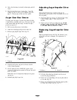
Replacing Auger/Impeller Drive Belt
16
. . . . . . . . . .
Replacing Traction Drive Belt
17
. . . . . . . . . . . . . . . .
Adjusting Traction Drive
18
. . . . . . . . . . . . . . . . . . . .
Adjusting Speed Selector
18
. . . . . . . . . . . . . . . . . . . .
Replacing Spark Plug
18
. . . . . . . . . . . . . . . . . . . . . . .
Storage
19
. . . . . . . . . . . . . . . . . . . . . . . . . . . . . . . . . . . . .
Warranty
20
. . . . . . . . . . . . . . . . . . . . . . . . . . . . . . . . . . . .
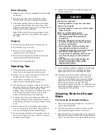
WARNING
The engine exhaust from this product contains
chemicals known to the State of California to
cause cancer, birth defects, or other reproductive
harm.
Introduction
Thank you for purchasing a Lawn-Boy product.
All of us at Lawn-Boy want you to be completely satisfied
with your new product, so feel free to contact your local
Authorized Service Dealer for help with service, genuine
Lawn-Boy parts, or other information you may require.
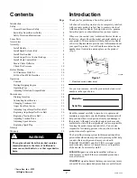
Whenever you contact your Authorized Service Dealer or
the factory, always know the model and serial numbers of
your product. These numbers will help the Service Dealer
or Service Representative provide exact information about
your specific product. You will find the model and serial
number decal located in a unique place on the product
(Fig. 1).
m–2592
1
Figure 1
1.
Model and serial number decal
For your convenience, write the product model and serial
numbers in the space below.
Model No:
Serial No.
Read this manual carefully to learn how to operate and
maintain your product correctly. Reading this manual will
help you and others avoid personal injury and damage to
the product. Although Lawn-Boy designs, produces and
markets safe, state-of-the-art products, you are responsible
for using the product properly and safely. You are also
responsible for training persons who you allow to use the
product about safe operation.
The Lawn-Boy warning system in this manual identifies
potential hazards and has special safety messages that help
you and others avoid personal injury, even death.
DANGER, WARNING and CAUTION are signal words
used to identify the level of hazard. However, regardless
of the hazard, be extremely careful.
DANGER signals an extreme hazard that will cause
serious injury or death if the recommended precautions
are not followed.
WARNING signals a hazard that may cause serious injury
or death if the recommended precautions are not followed.


