background image

Quick Operation Guide of Digital Video Recorder 

6/MNO/PLAY 

Enter numeral “6”; 

Enter letters “MNO”; 

Playback, for direct access to all-day playback interface. 

7/PQRS/REC 

Enter numeral “7”; 

Enter letters “PQRS”; 

Open the manual record interface. 

8/TUV/PTZ 

Enter numeral “8”; 

Enter letters “TUV”; 

Access PTZ control interface. 

9/WXYZ/PREV 

Enter numeral “9”; 

Enter letters “WXYZ”; 

Multi-channel display in live view. 

0/A 

Enter numeral “0”; 

Shift the input methods in the editing text field. (Upper and 

lowercase, alphabet, symbols or numeric input). 

DIRECTION


The DIRECTION buttons  are used to navigate between different 

fields and items in menus.   

In the Playback mode, the Up and Down button is used to speed up 

and slow down recorded video. The Left and Right button will select 

the next and previous record files. 

In Live View mode, these buttons can be used to cycle through 

channels. 

In PTZ control mode, it can control the movement of the PTZ 

camera. 

ENTER 

The ENTER button is used to confirm selection in any of the menu 

modes.   

It can also be used to 

tick 

checkbox fields. 

In Playback mode, it can be used to play or pause the video. 

In single-frame Playback mode, pressing the button will advance the 

video by a single frame. 

In Auto-switch mode, it can be used to stop /start auto switch. 

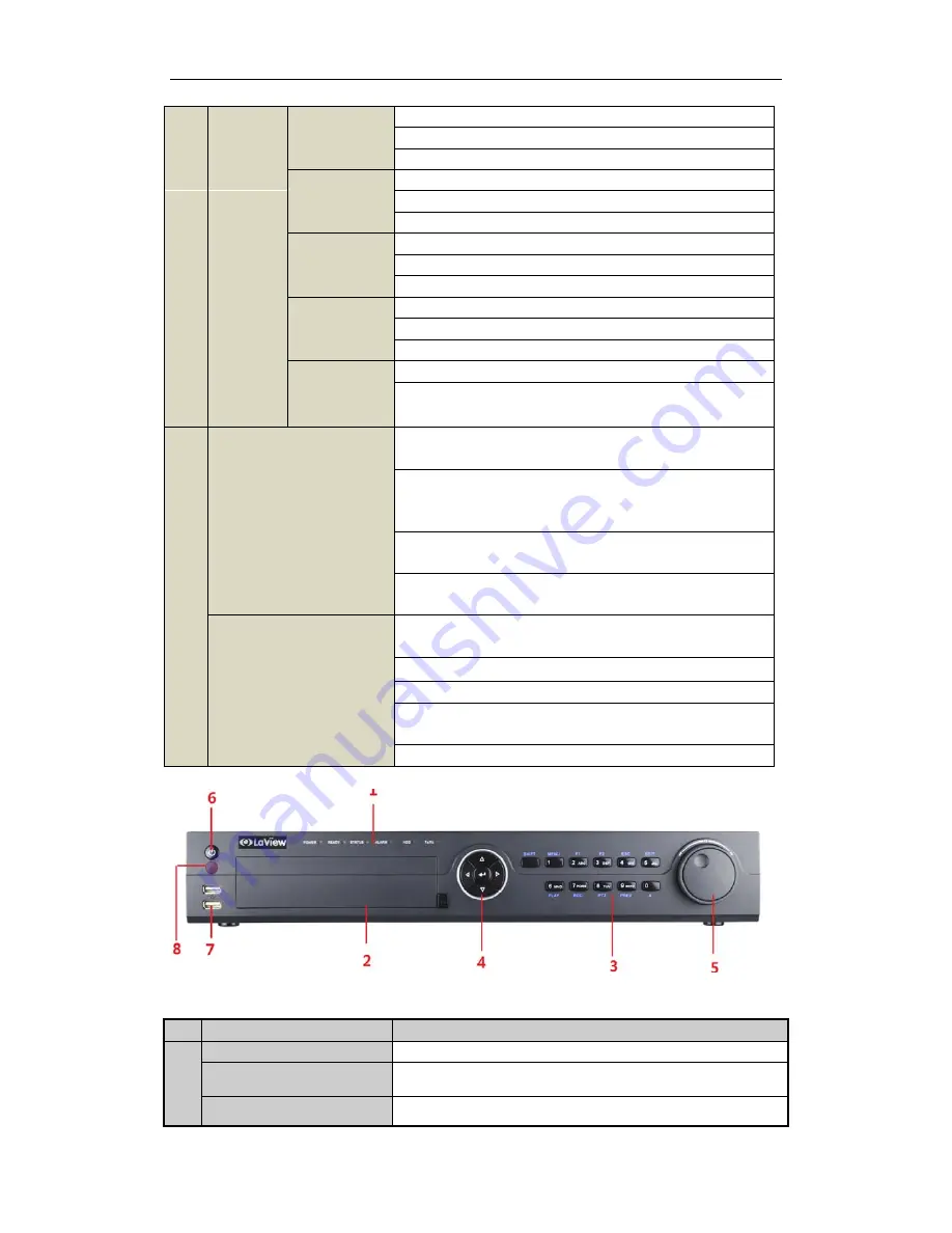
Front Panel of 16CH 

Description of Front Panel 

No. 

Name 

Function Description 

POWER 

Power indicator lights in green when DVR is powered up. 

READY 

Ready indicator is normally green, indicating that the DVR is 
functioning properly. 

STATUS 

Indicator turns green when DVR is controlled by an IR remote control 

Summary of Contents for Digital Video Recorder

Page 1: ...Digital Video Recorder Quick Operation Guide...

Page 2: ...brackets for rack mounting 2 Ensure there is ample room for audio and video cables 3 When installing cables ensure that the bend radius of the cables are no less than five times than its diameter 4 C...

Page 3: ...de of Digital Video Recorder 2 3 Connect the power cable to the HDD 4 Place the HDD on the bottom of the device and then fasten the screws on the bottom to fix the HDD 5 Re install the cover of the DV...

Page 4: ...mouse and USB Hard Disk Drive HDD 4 Composite Keys SHIFT Switch between the numeric or letter input and functions of the composite keys Input letter or numbers when the light is out Realize functions...

Page 5: ...and slow down recorded video The Left and Right button will select the next and previous record files In Live View mode these buttons can be used to cycle through channels In PTZ control mode it can c...

Page 6: ...tch between the numeric or letter input and functions of the composite keys Input letter or numbers when the light is out Realize functions when the light is red 1 MENU Enter numeral 1 Access the main...

Page 7: ...ode it can control the movement of the PTZ camera ENTER The ENTER button is used to confirm selection in any of the menu modes It can also be used to tick checkbox fields In Playback mode it can be us...

Page 8: ...r turning on off the device 11 GND Ground HDS 16 Channel Back Panel No Item Description 1 VIDEO IN HD SDI interface for video input 2 VIDEO OUT BNC connector for video output 3 AUDIO IN RCA connector...

Page 9: ...wer Switch Switch for turning on off the device 12 GND Ground 13 LINE IN BNC connector for audio input 14 eSATA Connects external SATA HDD CD DVD RM 15 RS 232 Interface Connector for RS 232 devices 16...

Page 10: ...and hold the orange part of the pluggable block insert signal cables into slots and release the orange part Ensure signal cables are in tight 3 Connect pluggable block back into terminal block Note Th...

Page 11: ...4CIF CIF Sub stream 4CIF non real time CIF QCIF QVGA Frame rate Main stream 1 16 fps Real time frame rate Sub stream 1 16 fps Real time frame rate Video bitrate 32 Kbps 16 Mbps Audio output 1 ch RCA L...

Page 12: ...0P30 720P25 Audio compression G 711u Audio input 4 ch RCA 2 0 Vp p 1 K Two way audio in 1 ch RCA 2 0 Vp p 1 K Video Audio output HDMI VGA output 1920 1080 60 Hz 1080P 1280 1024 60 Hz 1280 720 60 Hz 10...

Page 13: ...isk External interface Network interface 1 10M 100M 1000M self adaptive Ethernet interface Serial interface RS 232 RS 485 Keyboard USB port 3 USB2 0 Alarm in out 16 4 General Power supply 100 240VAC 4...

Page 14: ...it Rate Storage Used 96K 42M 128K 56M 160K 70M 192K 84M 224K 98M 256K 112M 320K 140M 384K 168M 448K 196M 512K 225M 640K 281M 768K 337M 896K 393M 1024K 450M 1280K 562M 1536K 675M 1792K 787M 2048K 900M...

Page 15: ...6CH DVR is shown below Startup and Shutdown Proper startup and shutdown procedures are crucial to expand the service time of the DVR To start the DVR Check the power supply is plugged into an electric...

Page 16: ...s are provided on screen in Live View mode to indicate different camera status These icons include Live View Icons In the live view mode there are icons at the right top of the screen for each channel...

Page 17: ...recording is configured by default in this mode Playback Play back the record files of a specific channel in the live view menu Instant playback by channel Choose a channel under live view using the m...

Page 18: ...can be used to control playing process The channel and time selection menu will display by moving the mouse to the right of the playback interface Just tick the channel or channels if you want to swi...

Page 19: ...Quick Operation Guide of Digital Video Recorder 18 3 Check backup result Choose the record file in Export interface and click button to check it...

Reviews: