Laurell WS-400 Lite Series Operation Manual Download Page 35

Laurell Technologies  
Operations Manual WS-400 Lite Series


All information contained in this manual is the property of Laurell Technologies Corporation® and is NOT to be edited, reproduced or 

distributed without express written permission from a corporate officer. 

35 

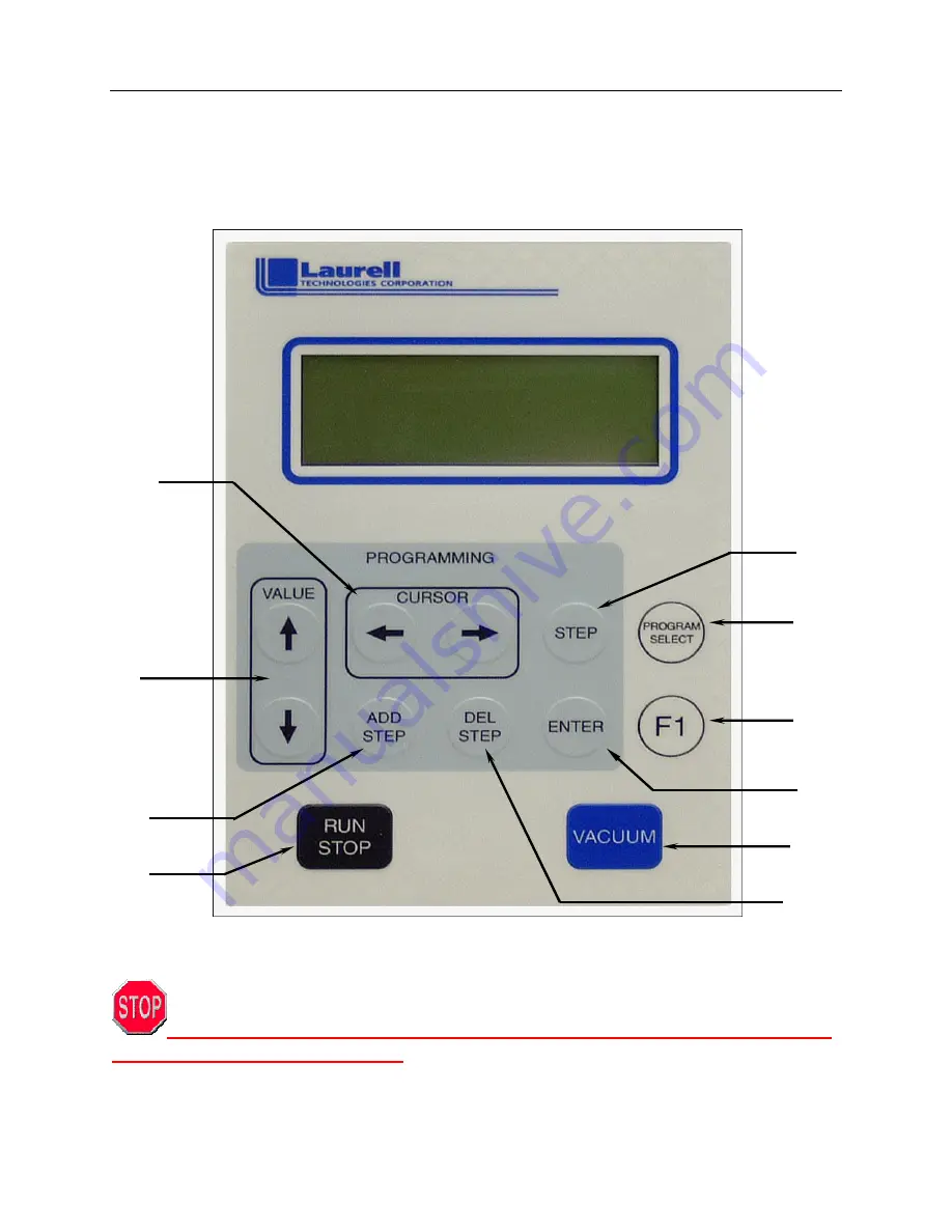
SECTION 3.3 - KEYPAD 

All operator interface actions are initiated through the membrane switch keypad, figure 
3-5.  The function of each key is as follows: 


Figure 3-5 

KEYPAD 

NEVER flood or spray solvent such as acetone or any other type of cleaner 

directly onto the keypad surface.  

Doing so may cause keypad failure

.  

Always wet a wipe or cloth with the solvent and gently wipe the keypad surface.

10 

Summary of Contents for WS-400 Lite Series

Page 1: ...ies Corporation and is NOT to be edited reproduced or distributed without express written permission from a corporate officer 1 WS 400 LITE SERIES SPIN PROCESSOR OPERATION MANUAL P N 10070021F6 Februa...

Page 2: ...Lid closure interlock Door latch on 8 and 15 series Motor seal purge interlock Nitrogen or Clean Dry Air is required Automatic power reduction after 10 minutes of non use Step time resolution of 0 1 s...

Page 3: ...TIAL EXPOSURE HAZARDS 12 1 5 1 ELECTRICAL HAZARDS 12 1 5 2 STATIC ELECTRICITY BONDING AND GROUNDING 13 1 5 2 1 BONDING 13 1 5 2 2 GROUNDING 13 1 5 3 MOVING PARTS HAZARDS 14 1 5 4 AUDIO NOISE HAZARDS 1...

Page 4: ...INTERLOCK 33 3 2 3 SEAL PURGE INTERLOCK 34 3 2 4 POWER ON LID CHECK 34 3 3 KEYPAD 35 3 3 1 OPERATIONAL KEYS 36 3 4 THE LCD DISPLAY 38 3 4 1 LINE ONE OF LCD DISPLAY 39 3 4 2 LINE TWO OF LCD DISPLAY 40...

Page 5: ...ted reproduced or distributed without express written permission from a corporate officer 5 SECTION 5 APPENDIX 59 5 1 1 INSTALLATION WS 400 6 8 LITE 59 5 1 2a INSTALLATION WS 400 6 8 LITE INDECK 60 5...

Page 6: ...ever possible turn off and lockout gases chemical delivery valves and electrical power before service or maintenance is performed Possible hazards associated with the spin processor system are Electri...

Page 7: ...iated with the spin processor system are clearly labeled on the equipment and in this manual using the preferred hazard warning trilogy of alert words pictograms and avoidance techniques This hazard w...

Page 8: ...taken See Figure 1 2B Caution Figure 1 2B CAUTION ALERT WARNING Depicted by black lettering on an orange background This indicates that an immediate hazard exists and special precautions are necessary...

Page 9: ...how the hazard may be avoided Laurell Technologies Corporation has adopted a series of pictograms used to identify various hazards which may be present in the spin processor These icons appear in the...

Page 10: ...Off circuit it should be powered by a system with EMO capability If your safety department or policies allow simply having the incoming power plug far enough away from the spin processor properly labe...

Page 11: ...button to immediately interrupt system power EMO Figure 1 3 EMO Emergency Machine Off PROCEDURE 1 4 PROTECTIVE APPAREL Always wear personal protective equipment when handling any potentially hazardou...

Page 12: ...onents are located internally and electrical power is distributed throughout the spin processor system Access can only be gained by removal of the bottom panel which is secured by screws Only LTC fact...

Page 13: ...rformed with the spin processor system power OFF There are NO maintenance tasks that require servicing of the spin processor while it is energized 1 5 2 STATIC ELECTRICITY BONDING AND GROUNDING WARNIN...

Page 14: ...ions were measured to be 51 dB A Readings of less than 80 dB A are considered non hazardous 1 5 5 CHEMICAL HAZARDS AND COMPATIBILITY The following section outlines some general guidelines for using ch...

Page 15: ...or arcing electrical equipment Keep all chemicals in a well ventilated area preferably in a cabinet designed for such storage WARNING Flammable liquids should be stored and transported in approved saf...

Page 16: ...strointestinal pain cramps nausea vomiting and diarrhea may also result The single lethal dose for a human adult about 250 ml 8 ounces Skin Contact May cause irritation with redness and pain May be ab...

Page 17: ...Sheets Inhalation Produces damaging effects on the mucous membranes and upper respiratory tract Symptoms may include irritation of the nose and throat and labored breathing May cause lung edema a medi...

Page 18: ...SAFETY PRECAUTIONS Full compliance with the following safety practices and those appearing earlier in this chapter is expected 1 Never work alone on live electrical circuits You must be within sight...

Page 19: ...cordance with OSHA and local state and federal codes 12 Operating personnel must NOT remove covers or panels Only qualified maintenance personnel may make component replacements and internal adjustmen...

Page 20: ...d MSDS NOTE Laurell Technologies Corporation recommends that copies of the MSDS be kept with this manual and be made available to your employees There are several websites dedicated to providing chemi...

Page 21: ...ribed below are available for controlling these process by products Thermal oxidizers convert the effluent gases into other compounds using either flame combustion or a heated catalytic process The fl...

Page 22: ...Manual WS 400 Lite Series All information contained in this manual is the property of Laurell Technologies Corporation and is NOT to be edited reproduced or distributed without express written permiss...

Page 23: ...another output from the same regulator Vacuum 25 28 635 711 mm Hg of vacuum with a flow volume of 4 5 SCFM 0 11cm m 0 Hg Exhaust see section 2 1 8 below Drain Open to atmosphere NOT restricted by a va...

Page 24: ...rell Chamber Drain Port 25 71M3 5 to 2 5 PP Chemical Solvent Note These measurements were taken in the exhaust duct 3 inches from the system after the first elbow 2 1 9 VACUUM PUMP OPTION LTC provided...

Page 25: ...sure regulator and a check valve 5 PSI breaking pressure be installed on all supply tubing connected to the spin processor Refer to installation drawing s in Section 5 for guidance 2 2 1 SPIN PROCESSO...

Page 26: ...r distributed without express written permission from a corporate officer 26 Installation Safety Caution WARNING Caution an extreme electrical hazard will exist if this system is immersed in liquid Th...

Page 27: ...ion contained in this manual is the property of Laurell Technologies Corporation and is NOT to be edited reproduced or distributed without express written permission from a corporate officer 27 2 2 2...

Page 28: ...ain configuration Exhaust is optional on the LITE model Figure 2 2B is the down flow exhaust option An exhaust source of approximately 0 5 to 2 5 H2O column as measured with a differential pressure ga...

Page 29: ...ies All information contained in this manual is the property of Laurell Technologies Corporation and is NOT to be edited reproduced or distributed without express written permission from a corporate o...

Page 30: ...ox assembly to the spin processor Two cables and one vacuum sensor hose are required which can be detached at the rear of the remote control box see Figure 2 3A Figure 2 3A INDECK CONTROLLER REAR VIEW...

Page 31: ...te is shown in program mode only Figure 3 1 INITIAL DISPLAY A vacuum interlock assures that vacuum is activated before any program can run and vacuum will not disengaged until the wafer comes to a com...

Page 32: ...circuit breaker should never trip If the circuit breaker does trip a visual and mechanical inspection of the unit should be performed before resetting the circuit breaker This circuit breaker also se...

Page 33: ...ng the program will be halted at that point and an E04 error message will appear on the LCD display1 Once vacuum has been re established it is necessary to press the RUN STOP key on the keypad to re s...

Page 34: ...e is monitored by a pressure sensor interlock This interlock will report an E10 error if the pressure should drop below the 60 PSI 4 1 bar requirement during operation The interlock will not allow a n...

Page 35: ...from a corporate officer 35 SECTION 3 3 KEYPAD All operator interface actions are initiated through the membrane switch keypad figure 3 5 The function of each key is as follows Figure 3 5 KEYPAD NEVER...

Page 36: ...the PGM mode step acceleration speed and optional valves are operational The time value is ignored in the PGM mode The user can manual step through a program while it is running by pressing the STEP k...

Page 37: ...gramming of the new step This key is disabled when the maximum number of steps currently 51 in a program is reached or in the setup mode and LOCK is set to one 1 9 Cursor Left Right Active in PGM mode...

Page 38: ...A ACTUAL LCD DISPLAY VIEW Figure 3 6B LCD DISPLAY LAYOUT Normal Run mode Program A running Running step 1 of 7 steps Vacuum Set point time Actual RPM Run time of step Set point RPM Valves 1 4 and 8 ac...

Page 39: ...s OFF or END will allow changing between the program and run modes The program mode is used to modify or display the information for each step in a program STEP e g 001 003 displays the present step n...

Page 40: ...ed at the end of this line An error example would be when the spin processor s lid is left open the message LID will flash here See Figure 3 8 Figure 3 8 FLASHING LID DISPLAY 3 4 3 LINE THREE OF LCD D...

Page 41: ...resolution for each step is 0 1 seconds rpm display shows the actual RPM during each step in a program Figure 3 10 ACTUAL VALUES SECTION 3 5 PROGRAMMING 1 Fill out the enclosed programming sheet s 2 P...

Page 42: ...d This step is to get the chuck rotating at the dispense step spin speed 2 3 6 Same as step 1 Same as step 1 015 Dispense Step Spin speed same as step 1 Dispense time enough to coat substrate Dispense...

Page 43: ...ION OFF RUN Mode 1 Select the program to be run using the PROGRAM SELECT key A letter A through T 20 programs will be indicated in the upper right corner of the display 2 Place a wafer on the chuck an...

Page 44: ...mn below the base of the chuck Turn the chuck counter clockwise to remove see fig 3 12A and clockwise to install making sure the chuck is snug see fig 3 12B DO NOT OVER TIGHTEN especially Teflon Figur...

Page 45: ...tice 2 screw heads fig 3 14b Use a 9 64 Allen wrench to remove both screws and gently pull the chuck upward until it is free of the motor shaft adapter fig 3 14c Replacing the chuck is done by alignin...

Page 46: ...spin processors All models equipped with a HPD2 motor have an additional lid interlock which prevents the opening of the lid while the tool is in operation All HPD2 motors have an insert or bolt on ty...

Page 47: ...mple is meant to show how agitation programming is possible Call or email our sales department for details if you need a continuous agitation mode for your work EXAMPLE OF AGITATION PROGRAMMING Step T...

Page 48: ...Manual WS 400 Lite Series All information contained in this manual is the property of Laurell Technologies Corporation and is NOT to be edited reproduced or distributed without express written permiss...

Page 49: ...of residual moisture Any questions regarding the maintenance of your spin processor can be addressed at www support laurell com Care should be taken not to flood the process chamber during cleaning I...

Page 50: ...nter of the vacuum chuck Cleaning the vacuum path in this manner is dangerous and can cause significant damage to your spin processor 4 1 ERROR MESSAGES The detection of abnormal operating conditions...

Page 51: ...ermine if error is due to vacuum loss or motor speed Correct any obvious problems If condition persists contact Support at Laurell Technologies Corporation for assistance Vacuum source Seal Purge sour...

Page 52: ...corporate officer 52 functioning properly the following procedure can be performed to clean the valve NOTE FOLLOW THIS PROCEDURE CLOSELY AND BE CAREFULL NOT TO LOSE THE 3 SMALL O RINGS 1 Carefully rem...

Page 53: ...e actuation spring 6 Remove the piston by carefully sliding it out of the center assembly Keep track of all parts while cleaning so as not to lose any for reassembly The parts can be taken apart and h...

Page 54: ...e chuck and press the vacuum key Using a bottle of DI water spray water around the periphery of the substrate where it meets the chuck while manually rotating the chuck Check to see if there is any le...

Page 55: ...and 200mm Chuck 4 1 4 CLEANING AND REPLACING THE CHUCK O RING To remove the o ring from the chuck insert a thin blunt instrument or o ring puller into the o ring groove and pull upward Be careful not...

Page 56: ...osed to the relatively smooth texture of the Viton material some Viton O rings are brown in color The vacuum chuck s O ring seal should NEVER deflect 0 002 50 microns If you experience substrate defle...

Page 57: ...han acceleration When programming such steps it is necessary to select a deceleration rate that the motor can achieve This usually requires setting the acceleration index in the 1 to 5 range If this i...

Page 58: ...d without express written permission from a corporate officer 58 4 1 6 CALIBRATION MODE Calibration is used to adjust rotation performance by allowing fine tuning of the motor controller for large cha...

Page 59: ...information contained in this manual is the property of Laurell Technologies Corporation and is NOT to be edited reproduced or distributed without express written permission from a corporate officer 5...

Page 60: ...es All information contained in this manual is the property of Laurell Technologies Corporation and is NOT to be edited reproduced or distributed without express written permission from a corporate of...

Page 61: ...es All information contained in this manual is the property of Laurell Technologies Corporation and is NOT to be edited reproduced or distributed without express written permission from a corporate of...

Page 62: ...s All information contained in this manual is the property of Laurell Technologies Corporation and is NOT to be edited reproduced or distributed without express written permission from a corporate off...

Page 63: ...he property of Laurell Technologies Corporation and is NOT to be edited reproduced or distributed without express written permission from a corporate officer 63 Figure 5 1 4 INSTALLATION TUBING FOR IN...

Page 64: ...sure gauge Clear polycarbonate wafers many sizes available Clear polycarbonate lid Custom vacuum non vacuum chucks Manual syringe kit Manual EBR syringe High performance drive motors Higher speed up t...

Reviews: