background image


- 23 - 

Example: Transmit the digital reading in amps and as 4-20 mA from an AC current transformer 

Application: 

Use a 200:5 (200A in, 5A out) AC current transformer.  Digitally transmit the AC 

current reading in amps with 0.1A resolution. Also transmit a 4-20 mA signal corresponding to 
0-100A. 


Solution:


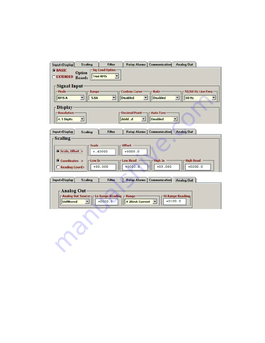
Jumper signal conditioner for 5.000 A current range and AC coupling. 


Under  “Input+Display”  tab,  set  “Option  Board”  to  True  RM

S,  Mode  to  RMS  A,  Range  to 

5.0A, “Decimal Point” to dddd.d, and “50/60 Hz Line Freq” to 60 Hz to reject 60 Hz noise.


Under Scaling tab, if Coordinates is selected, set “High In” to 5.000A and “High Read” to 

200.0A. For this application, Coordinates is the easiest, most intuitive scaling method. 


Under Scaling tab, if “Scale, Offset” method is selected, set Scale to 0.4. The reason is that 

a  5A  full-scale  input  corresponds  to  5,000  input  counts,  where  each  input  count  is  
1 mA (as for the 5A scale of a 4-digit meter). These 5,000 input counts need to correspond 
to 2,000 output counts, where each output count is 0.1A. 


Under “Analog Out” tab, set Range to “4

-

20 mA current”, “Lo Range Reading” to 0.0A, and 

“Hi Range Reading” to 100.0A.


Summary of Contents for LTE Series

Page 1: ...SERIES TRANSMITTERS Analog Input Ethernet Isolated 4 20 mA Outputs USER MANUAL LAUREL Electronics Inc 3183 G Airway Ave Costa Mesa CA 92626 USA Tel 714 434 6131 Fax 714 434 3766 Website www laurels c...

Page 2: ...00 0 V RMS Amperes RMA1 2 0000 mA RMA2 20 000 mA RMA3 200 00 mA RMA4 5 000 A Range not ETL certified Process Ratio Signals 4 20 mA 0 10V etc P 4 20 mA in 4 20 mA out P1 Custom Scaling Specify min inpu...

Page 3: ...Your Transmitter Case 19 11 DC Signal Conditioner Board 20 12 AC Rms Signal Conditioner Board 22 13 Load Cell Signal Conditioner Board 24 14 Thermocouple Signal Conditioner Board 26 15 RTD Ohms Signa...

Page 4: ...g separate manuals Ethernet Manual Covers Ethernet Node discovery and setup using Node Manager PC Software or the Web Server Software built into each Node Required for use of Ethernet transmitters and...

Page 5: ...reading Isolated Ethernet communications are standard via an RJ45 connector for a 10 100BaseT interface Four serial communication protocols are understood by our transmitters Modbus TCP Modbus RTU Mo...

Page 6: ...entiate it from other input and output connectors The 12 32 Vac or 10 48 Vdc power connector is colored Black This transmitter has no power switch It will be in operation as soon as power is applied T...

Page 7: ...raw more than the rated transducer excitation output current will shut down the output Jumpers on analog signal conditioner boards are described in later manual sections Normal operation as opposed to...

Page 8: ...8 P5...

Page 9: ...ws based software allows Node and Device discovery uploading editing downloading and saving of setup data execution of commands under computer control listing plotting and graphing of data and compute...

Page 10: ...Setup screen will appear In the Communications Setup screen select Transmitter LTE as the Device Type Ethernet as the Communication Type any of the protocols listed Upon clicking on Ethernet for the f...

Page 11: ...you have passed the Windows Firewall With a direct cable connection to the PC only one Ethernet Node will be listed With a LAN connection multiple Ethernet Nodes may be discovered on the same LAN Sele...

Page 12: ...t your Node and you can assign a descriptive name to it such as Tank Farm The default name is the Node s unique MAC address You can also use this tab to change your Node s communication settings Press...

Page 13: ...n a remote LAN over the Internet port forwarding must first be set up for the router that controls the remote LAN The default port numbers pro grammed into our Nodes are UDP port 63179 for Node discov...

Page 14: ...lay the current reading Press the F1 key for help with any highlighted item For ratiometric operation with a DC signal conditioner set the Signal Input Mode to Ratio In this mode the transmitter track...

Page 15: ...erically and 3 Reading Coor dinates of 2 points method which captures actual readings Click on the Filter tab to set to set up filtering for your readings The filter time constant can be automatic be...

Page 16: ...p with any highlighted item Click on the Analog Out tab to scale your analog output which is standard Under Range select 0 20 mA Current 0 10V Voltage or 4 20 mA Type in your Lo Range Reading and Hi R...

Page 17: ...ree formats to display input data on your PC monitor Use the Pause and Continue buttons to control the timing of data collection then press Print for a hardcopy on your PC printer List presents the la...

Page 18: ...18 Graph The Jumpers pull down menu shows jumper positions for the selected signal conditioner boards and the main board duplicating information in this manual...

Page 19: ...please see the next five sections of this manual Note that all ranges of all signal conditioner boards are factory calibrated with calibration factors stored in EPROM on the board 2 On the main board...

Page 20: ...t associated with a capital letter For process DC ratio three scaling methods can be selected in Instrument Setup Software 1 Scale and offset 2 Coordinates of 2 points and 3 Reading coordinates of 2 p...

Page 21: ...r for 200 00 mV range Under Input Display tab set Option Board to DC Mode to DC V Range to 0 2V Decimal Point to dddd d and 50 60 Hz Line Freq to 60 Hz to reject 60 Hz noise Under Scaling tab if Coord...

Page 22: ...but reinstall before closing the case To minimize noise pickup the input signal wiring should utilize a shielded twisted pair and the shield should be connected to signal low at the rms board as illus...

Page 23: ...to dddd d and 50 60 Hz Line Freq to 60 Hz to reject 60 Hz noise Under Scaling tab if Coordinates is selected set High In to 5 000A and High Read to 200 0A For this application Coordinates is the easi...

Page 24: ...al Operation is ratiometric with automatic compensation for changes in excitation voltage For DC microvolt applications a scale factor of 1 and an offset of 0 are used for direct read ings in microvol...

Page 25: ...nal conditioner for 50 000 mV range Set power supply to 10V excitation Under Input Display tab set Mode to Strain range to 50 0mV decimal point to 3 places and 50 60 Hz Line Freq to 60 Hz to reject 60...

Page 26: ...rd Revision A 1 Use 2 5 mm 0 1 jumpers 2 Store spare jumpers on an unused jumper post The largest source of thermocouple reading errors are variations in the alloys used in commercial thermocouple wir...

Page 27: ...hermocouple Solution Jumper signal conditioner for Type K thermocouple Under Input Display tab set Mode to Thermocouple range to K deg C Resolution to 0 1 deg and 50 60 Hz Line Freq to 60 Hz to reject...

Page 28: ...tance Please see Section 6 for hookup diagrams In 2 wire hookup the transmitter senses the voltage drop across the load and both lead wires The effect of the lead wires can be measured and subtracted...

Page 29: ...higher Solution Jumper signal conditioner for Pt100 and 2 or 4 wire connection Under Input Display tab set Mode to RTD Range to ANSI deg F Resolution to 0 1 deg and 50 60 Hz Line Freq to 60 Hz to rej...

Page 30: ...compared if deviation is set to zero The reading is the count in engineering units that is transmitted digitally and is also used for analog output For example if the transmitted reading is in gallons...

Page 31: ...and Span Hysteresis These define how Setpoint and Deviation are to be combined to set Alarm State Split Hysteresis for heater control Band Deviation for component testing In Band Deviation the relay...

Page 32: ...RC time constants no filter 0 1 sec 0 2 sec 0 4 sec 0 8 sec 1 6 sec 3 2 sec and 6 4 sec The longer time constants provide superior noise filtering at the expense of fast response time Note that filte...

Page 33: ...re Instead use the Scaling tab under Setup Here you can enter values for Scale and Offset for a specific range These corrections apply to resistance not to RTD temperature To calibrate RTD temperature...

Page 34: ...ual meters 2 0 FRAMING Modbus RTU Message frames are separated by a silent interval of at least 3 5 character times If a silent interval of more than 1 5 character times occurs between two characters...

Page 35: ...e 00 01 Returns Hi word of Alarm status 00 02 Returns Lo word of Alarm status 00 03 Returns Hi word of Measurement value 00 04 Returns Lo word of Measurement value 00 05 Returns Hi word of Peak value...

Page 36: ...not addressed to this Slave Excludes bad LRC CRC parity error or length 3 00 0C 00 00 Checksum Error Count Returns total number of messages with bad LRC CRC parity or length 3 errors detected on the...

Page 37: ...RC Hi Byte RA Register Address SF Sub Function CR Carriage Return NR Number of Registers EC Error Code LF Line Feed NB Number of bytes LRC ASCII Checksum Modbus RTU Format FC Action 3 5 Char Byte Numb...

Page 38: ...U 010 001 Modbus ASCII 020 001 Restart Com munications Request Response 010800010000B1CB 010800010000B1CB 010800010000F6crlf 010800010000F6crlf Meter Reset Request Response 01050001FF00DDFA None 01050...

Page 39: ...ished even when it follows the last digit Adding a Line Feed Character to the Basic Format Printers and other devices that receive the data may require a line feed character LF following the CR The li...

Page 40: ...ould have a termination resistor installed It is necessary to set up each device on the bus with a different address from 1 to 31 To command a particular device its address is used in conjunction with...

Page 41: ...ations Address Code from 1 to V follows the to indicate the device address number from 1 to 31 Device Address Code Device Address Code Device Address Code 1 2 3 4 5 6 7 8 9 10 11 1 2 3 4 5 6 7 8 9 A B...

Page 42: ...emory F Write bytes to RAM Memory DPM and Scale meter only R Read bytes from Upper RAM Memory Q Write bytes to Upper RAM Memory X Read words from Non Volatile Memory W Write words to Non Volatile Memo...

Page 43: ...hex charac ters as shown below under RAM MEMORY ADDRESSES AND DATA DEFINITIONS General Reading and Writing Nonvolatile Memory Data Nonvolatile data is read and written as a continuous string of words...

Page 44: ...in board Programming Via PC using Instrument Setup software and Ethernet cable Analog to Digital Conversion Conversion rate 60 sec at 60 Hz power 50 sec at 50 Hz power Input resolution 16 bits 65 536...

Page 45: ...Input Resistance Input Error 200 00 mV 2 0000 V 20 000 V 200 00 V 1 G 1 G 10 M 10 M 0 01 of full scale 2 counts 300 0 V 600 0 V 10 M 0 4 V 2 0000 mA 20 000 mA 200 00 mA 100 10 1 0 01 of full scale 2...

Page 46: ...9 F RTD connection 2 3 or 4 wire Span tempco 0 003 of reading C Zero tempco 0 03 deg deg Sensor lead resistance tempco per conductor 2 wire 10 deg deg up to 10 Sensor lead resistance tempco per conduc...

Page 47: ...10 C 0 17 F S 46 to 68 C 51 to 213 F 0 12 C 0 22 F R 45 to 1768 C 49 to 3214 F 0 17 C 0 31 F Resistance Input Range 1 Count Excitation Input Error 0 20 000 0 200 00 0 2000 0 0 20000 0 200 00 k 0 2 00...

Page 48: ...5 Mishandling or abuse The warranty set forth above is exclusive and no other warranty whether written or oral is expressed or implied Laurel specifically disclaims implied warranties of merchantabili...

Reviews: