background image

LAUNCH                                                               X-631/X-631+ Wheel Aligner 

iii 

inspected as to their operational condition. 

 
• The necessary personal safety equipment for 

operating, maintenance and repair personnel is 
available and being worn. 

 
• The operating instructions are always in a legible 

condition and are completely available at the 
machine location. 

 
• The machine is only operated, maintained and 

repaired by qualified and authorized personnel. 

 
• This personnel is instructed routinely in all pertaining 

questions of work safety and environmental 
protection, and knows the operating instructions, 
especially the safety instructions contained therein. 

 
• All safety and warning labels attached to the 

machine are not removed and are legible. 

Concrete safety instructions 
and applied symbols 

 
Concrete safety instructions are provided in the 
following operating instructions which will point out 
any unavoidable remaining risks during the machine 
operation. These remaining risks contain hazards for: 
 
Persons 
Product and machine 
The environment 
 
Symbols used in the operating instructions should 
draw attention to the safety signs! 
 

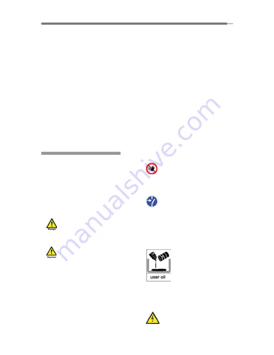
This symbol points out that specifically 

personal injury risks may be anticipated (Mortal 
danger, risk of injuries). 

This symbol signifies that especially 

hazards for the machine, material and the 
environment may be encountered. 


The most important objective of the safety signs 
exists in the prevention of personal injuries. 

If the warning triangle with the wording “danger” is on 
a safety notice, hazards for the machine, material and 
the environment are not excluded. 
If the warning triangle with the wording “caution” is on 
a safety reference, personal injuries are not 
anticipated. 

 
The applied symbol cannot replace the text of the 
safety reference. The text must therefore always be 

completely read! 
 

Basic safety measures during normal 
operations: 


The machine may only be operated by trained and 
authorized personnel who know the operating 
instructions and are capable of working with them! 
Prior to switching the machine on, check and verify 
that: 
Only authorized personnel are located within the 
working range of the machine. 
No one can be injured when the machine is activated! 
Check the machine for visible damages prior to use 
and verify that it is only operated in perfect condition! 
Report any problems immediately to the supervisor! 
Prior to each operating start, check and verify that all 
safety equipment operates perfectly! 
 

Basic safety measures during service 
and maintenance: 

Adhere to the inspection and maintenance intervals 
specified in the operating instructions! 
 

Block access to the work area of the machine 

to unauthorized personnel prior to performing 
maintenance or repairs! Attach or set up a warning 
sign that points out maintenance or repair work! 
 

  Pull the power plug prior to any maintenance 

or repair work or switch off the main switch for the 
power supply and secure with a lock, if the power 
supply is installed. 
The key to this lock must be in the hands of the 
person that is completing the maintenance or repair 
work! Only use perfect load suspension and lifting 
equipment when replacing heavy machine parts! 
 

  Properly dispose of environmentally 

hazardous lubricants, coolants or cleaning agents! 


Working on the electrical equipment: 


Repairs on electrical equipment of the 

machine may only be performed by trained 

Summary of Contents for X-631 Plus

Page 1: ......

Page 2: ...request written permission to use Materials on this manual for purposes or for all other questions relating to this manual Copyright Information Copyright 2010 by Launch Tech Co Ltd All rights reserve...

Page 3: ...for it may cause permanent damage to the system z The wires inside the cabinet and the probe rod sensors are connected compactly Any disconnection may cause damage to the sensor Damage due to unauthor...

Page 4: ...ning triangle with the wording caution is on a safety reference personal injuries are not anticipated The applied symbol cannot replace the text of the safety reference The text must therefore always...

Page 5: ...in the chargers provided in the delivery Protect from water sprays Do not open or short circuit electrical contacts Do not use if the housing has been damaged or if the electrical contacts have been...

Page 6: ...1 Probe Rods 2 1 Wheel Clamps 2 3 Wheel Clamp Hanging Bracket 2 3 Turntables 2 3 Steering Wheel Holder 2 3 Brake Pedal Depressor 2 4 Calibrating Frame and its Converter Connector Optional 2 4 Basic O...

Page 7: ...peed driving z When the tire s steering knuckle or shock absorber are replaced z When the vehicle is impacted z When the vehicle has covered the first 3000km or 10000km Main Vehicle Alignment Paramete...

Page 8: ...steering will normally be designed with positive caster Thrust angle The thrust angle is defined according to the driven mode of vehicle z Rear wheel driven the thrust angle equals half of the toe in...

Page 9: ...vehicle adjustment z Language operating prompt function z Emergency power supply and in time charging function z The probe rods provide LCD display function z Electronic level function z Black box se...

Page 10: ...Rear camber f8 0 Thrust angle f5 0 Notes 1 The above measurement ranges can be confirmed only when the user follows the specified operation procedures Requirements on Surroundings Item Specification A...

Page 11: ...s at the sideboard of cabinet The power lead is at the rear of the lower compartment inside the cabinet The power socket is at the spacer board and near to the sideboard The switch power supply is als...

Page 12: ...tes the position of the bubble level as shown in Fig 2 7 Fig 2 7 The probe rod is level when the black float mark turns to OK as shown in Fig 2 8 Fig 2 8 Display for run out compensation To display th...

Page 13: ...usting knob to adjust the span between wheel claws and then attach the clamp to the wheel rim Adjust the knob to make the wheel clamp fixed on wheel rim tightly Use the wheel clamp tie to bind the whe...

Page 14: ...depressor is as shown in Fig 2 19 It is used to hold the brake pedal down Fig 2 19 Brake pedal depressor Calibrating Frame and its Converter Connector Optional They are mainly used to calibrate the p...

Page 15: ...ck absorber tie rod ball and steering mechanism for any loose or wear Then check to see if the tire pressure tire treads of the left and right wheels are alike Wheel Alignment Checking Perform the whe...

Page 16: ...l the probe rod by adjusting the bubble in the level gauge to the center position VII Plug the power cable of the Wheel Aligner into a standard power outlet of 3PIN Switch on the power supply of the c...

Page 17: ...the probe rod s position dropped the level adjustment should take the electronic level as the standard Help To provide the description of operating method and note Operating procedures Select the corr...

Page 18: ...tform for ride height measurement system in order to check if the ride height meets the design requirements of OEM Fig 4 8 Operating methods According to the prompts on the picture at the bottom of th...

Page 19: ...y keep the four wheels on the ground Shake the vehicle body keep four wheels cling to the ground the run out compensation operation is finished The interface displays the values of run out compensatio...

Page 20: ...fter finished 4 Push the vehicle back to the original position and then adjust all probe rods level Please click NEXT after finished Caster Swing Kingpin measurement is aimed at the front wheels which...

Page 21: ...Fig 4 17 Caution 1 Before perform kingpin measurement please install brake pedal depressor and lock the hand brake first in order to ensure the vehicle wheels cannot move remove the steering wheel ho...

Page 22: ...4 21 Fig 4 21 Note The system provides the dynamic measurement and display for these special values but the measurement result will not be saved in the database HELP for vehicle adjustment Click this...

Page 23: ...ndividual toe in is not displayed HELP for vehicle adjustment Click this button the screen will pop up an interface of HELP for vehicle adjustment the different adjusting methods for various vehicle m...

Page 24: ...reen Click NEXT button the screen will display the interface as shown in Fig 4 27 Fig 4 27 4 Put up the vehicle to position B2 according to the requirements of the manufacturer The screen display the...

Page 25: ...ll Steering wheel is not centered Steering wheel swings and Others Save To save the alignment data of the vehicle under test Vehicle plate number and Client name must be entered and Fault cause must b...

Page 26: ...splay left lateral offset right lateral offset axle offset front setback rear setback track width difference and wheelbase difference etc The interface is as shown in Fig 4 35 Fig 4 35 Select Vehicle...

Page 27: ...te all the corresponding information including previous testing information of client Ensure that you do want to delete the information before performing Delete operation Print Print client informatio...

Page 28: ...pplied in actual testing operation Demo version this version can in stand alone status simulate the testing process without external hardware equipments it hasn t testing ability only used to demonstr...

Page 29: ...face is as shown in Fig 4 45 Fig 4 45 Select Language The system has provided many languages to select The interface is as shown in Fig 4 46 Fig 4 46 Operating procedures Select your desired language...

Page 30: ...t this probe rod has been abnormal Status of probe rod In the Probe rod maintenance interface click the icon to enter the interface of the probe status Status of probe rod is used to display the commu...

Page 31: ...XT after finished Fig 4 53 Remove FL probe rod install FR probe rod on FL wheel and then adjust the probe rod level Click NEXT after finished Fig 4 54 Remove FR probe rod install LR probe rod on FL wh...

Page 32: ...match between the probe rod and the computer host Electronic Level Correction for Probe Rod In the interface of Probe Rod Maintenance please click the icon of Electronic Level Correction for Probe Rod...

Page 33: ...rompts on the screen please click NEXT button to sample data The interface is as shown in Fig 4 64 Fig 4 64 According to the prompts on the screen switch on the power supplies of FL and RL probe rods...

Page 34: ...n please click NEXT button to sample data The interface is as shown in Fig 4 70 4 70 According to the prompts on the screen install 4 probe rods and adjust them level switch on all power supplies of p...

Page 35: ...click NEXT button to sample data The interface is as shown in Fig 4 76 Fig 4 76 According to the prompts on the screen turn the calibration frame shaft by 180 degrees install FL and FR probe rods and...

Page 36: ...dicates that the calibration is successful this time If the calibrated value of any one of and inclinometer is equal to zero it indicates that the calibration is not successful this time and it is req...

Page 37: ...y import this back up file Log Review Log is the important recorded information for the system running We can check the system conditions by viewing the log so we can say that the log is an important...

Page 38: ...ment System Setting for the detailed settings The interface is as shown in Fig 4 91 Fig 4 91 New Functions of X 631 Wheel Aligner Added Functions for X 631 Wheel Aligner No PC Mode and the correspondi...

Page 39: ...please press down key Previous and Next at the same time to enter the prompt interface for four probe rod working mode of No PC Mode Fig 4 95 Fig 4 96 After selecting working mode please press down k...

Page 40: ...rking mode toe in is of total toe in indicated by TT when the system uses four probe rod working mode toe in is of individual toe in indicated by T 8 When X 631 wheel aligner uses No PC Mode the displ...

Page 41: ...it and the monitor Please cleanout it with neutral detergent or dehydrated alcohol Avoid using oil or caustic product z Never disassemble the computer and move the inside cables and cards to avoid dam...

Page 42: ...on or warranty concerning LAUNCH automotive meters except as stated herein Disclaimer THE ABOVE WARRANTY IS IN LIEU OF ANY OTHER WARRANTY EXPRESSED OR IMPLIED INCLUDING ANY WARRANTY OF MERCHANTABILITY...

Page 43: ...Q D UHVLGHQWLDO LQVWDOODWLRQ 7KLV HTXLSPHQW JHQHUDWHV XVHV DQG FDQ UDGLDWH UDGLR IUHTXHQF HQHUJ DQG LI QRW LQVWDOOHG DQG XVHG LQ DFFRUGDQFH ZLWK WKH LQVWUXFWLRQV PD FDXVH KDUPIXO LQWHUIHUHQFH WR UDGLR...

Reviews: