background image

7

LAUNCH

                                Creader Professional CRP123 User's Manual

4

/

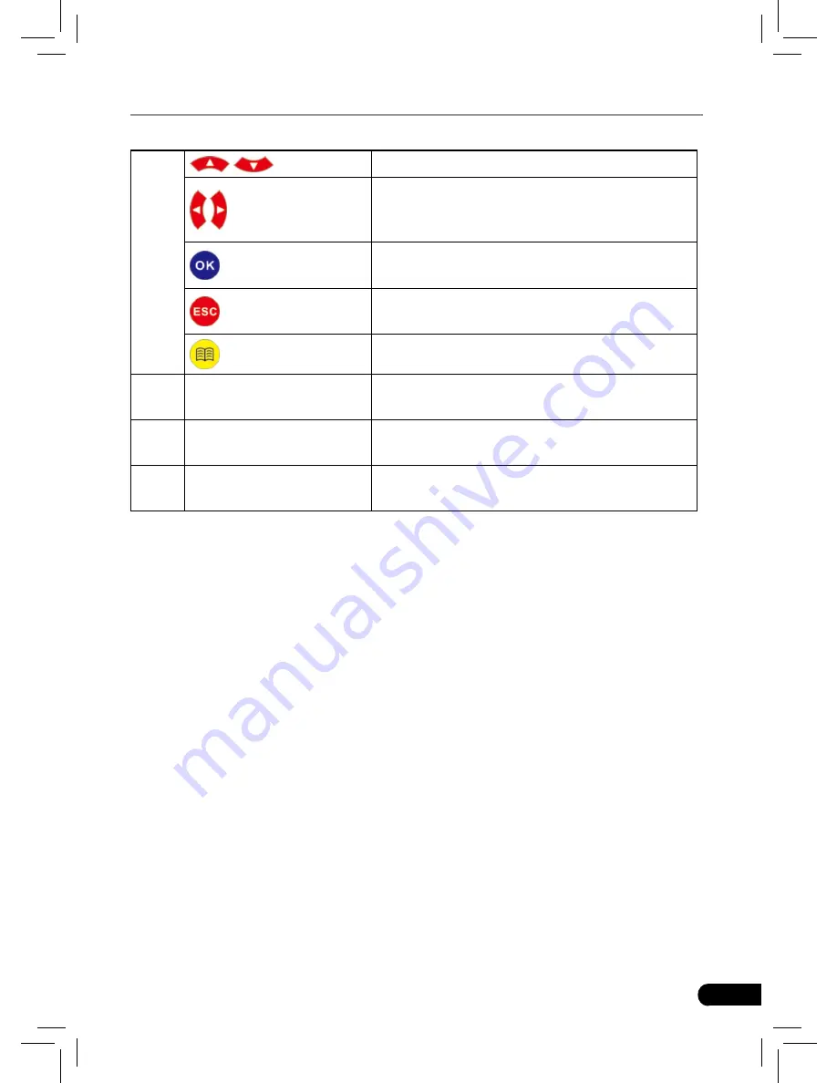
Move cursor up or down for selection.

/

Move cursor left or right for selection; Or 

turn page up or down when more than one 

page is displayed.
Confirms a selection (or action) from a menu 

list.
Exit the current program or return to the 

previous screen.
To retrieve the DTCs in the database.

5

USB port

To connect to PC to upload data or print test 

results.

6

TF card slot

Insert the TF card into it to read or write the 

data/file stored in TF card.

7

OBD-16 connector

To  connect  to  vehicle's  DLC(Data  Link 

Connector) via diagnostic cable.

3.2 Specifications

Screen: 3.5” TFT LCD display

• 

Working voltage: 9~18V

• 

Working current: <600mA

• 

Working temperature: -0 to 50°C (32 to 122 F°)

• 

Storage temperature: -20 to 70°C (-4 to 158 F°)

• 

Working humidity: 10%~90%

• 

Storage humidity: <80%

• 

3.3 Accessories Included

User’s Manual

1. 

TF card

2. 

TF card reader

3. 

USB cable

4. 

Summary of Contents for CRP123

Page 1: ...V1 00 002 2013 04 22 ...

Page 2: ...ay not use any trademark service mark domain name logo or company name of LAUNCH or any third party without permission from the owner of the applicable trademark service mark domain name logo or company name You may contact LAUNCH at www cnlaunch com or write to LAUNCH TECH CO LTD Launch Industrial Park North of Wuhe Avenue Banxuegang Bantian Longgang Shenzhen Guangdong P R China to request writte...

Page 3: ...ith the terms and conditions of this Agreement LAUNCH TECH CO LTD or its subsidiary licensing the Materials instead of LAUNCH grants to Customer a nonexclusive and nontransferable license to use for Customer s internal business purposes the Materials and the Document for which Customer has paid the required license fees Document means written information whether contained in user or technical manu...

Page 4: ...hout the express written authorization of LAUNCH v Disclose provide or otherwise make available trade secrets contained within the Materials in any form to any third party without the prior written consent of LAUNCH Customer shall implement reasonable security measures to protect such trade secrets To the extent required by law and at Customer s written request LAUNCH shall provide Customer with t...

Page 5: ...d the license granted herein shall remain effective until terminated Customer may terminate this Agreement and the license at any time by destroying all copies of Materials and any Document Customer s rights under this Agreement will terminate immediately without notice from LAUNCH if Customer fails to comply with any provision of this Agreement Upon termination Customer shall destroy all copies o...

Page 6: ...ns repairs or alterations to this unit or failure to strictly comply with LAUNCH operating and maintenance instructions LAUNCH shall not be liable for any damages or problems arising from the use of any options or any consumable products other than those designated as Original LAUNCH Products or LAUNCH Approved Products by LAUNCH Safety Precautions and Warnings To prevent personal injury or damage...

Page 7: ... is engaged Keep a fire extinguisher suitable for gasoline chemical electrical fires nearby Don t connect or disconnect any test equipment while the ignition is on or the engine is running Keep the CRP123 dry clean free from oil water or grease Use a mild detergent on a clean cloth to clean the outside of the CRP123 when necessary ...

Page 8: ...iptions 6 3 1 Outline of CRP123 6 3 2 Specifications 7 3 3 Accessories Included 7 4 Connection 8 4 1 Preparation 8 4 2 Install TF card 8 4 3 Connect CRP123 8 5 Diagnose 10 5 1 OBDII EOBD Diagnosing 10 5 1 1 Read Codes 11 5 1 2 Erase Codes 13 5 1 3 I M Readiness 14 5 1 4 Data Stream 15 5 1 5 View Freeze Frame 17 5 1 6 O2 sensor test 18 5 1 7 On board monitor test 19 5 1 8 EVAP System Test 20 5 1 9 ...

Page 9: ...ion Information 28 7 2 DTC Library 28 7 3 Abbreviation 29 7 4 Tool Information 30 7 5 About OBD 30 8 Update 31 8 1 User Registration 31 8 2 Register a passport 31 8 3 Fill in Product Information 33 8 4 Software Download 33 8 5 Software Update 34 8 6 Purchase Software 34 9 FAQ 35 ...

Page 10: ...ion of On Board Diagnostics called OBD I was developed by the California Air Resources Board ARB and implemented in 1988 to monitor some of the emission control components on vehicles As technology evolved and the desire to improve the On Board Diagnostic system increased a new generation of On Board Diagnostic system was developed This second generation of On Board Diagnostic regulations is calle...

Page 11: ...rouble Codes consist of a five digit alphanumeric code The first character a letter identifies which control system sets the code The second character a number 0 3 other three characters a hex character 0 9 or A F provide additional information on where the DTC originated and the operating conditions that caused it to set Here below is an example to illustrate the structure of the digits Figure 2 ...

Page 12: ...valuated by the OBD II system They are running periodic tests on specific systems and components to ensure that they are performing within allowable limits Currently there are eleven OBD II Readiness Monitors or I M Monitors defined by the U S Environmental Protection Agency EPA Not all monitors are supported in every vehicles and the exact number of monitors in any vehicle depends on the motor ve...

Page 13: ...to Ready or Complete after an appropriate drive cycle has been performed The drive cycle that enables a monitor and sets readiness codes to Ready varies for each individual monitor Once a monitor is set as Ready or Complete it will remain in this state A number of factors including erasing of diagnostic trouble codes DTCs with a code reader or a disconnected battery can result in Readiness Monitor...

Page 14: ...ehicle s factory service manual for specific enabling procedures OBD II Drive Cycle A specific mode of vehicle operation that provides conditions required to set all the readiness monitors applicable to the vehicle to the ready condition The purpose of completing an OBD II drive cycle is to force the vehicle to run its onboard diagnostics Some form of a drive cycle needs to be performed after DTCs...

Page 15: ...roduct Descriptions 3 1 Outline of CRP123 1 2 3 4 5 6 7 Figure 3 1 No Name Descriptions 1 Power indicator It will light up while CRP123 is energized 2 Communication indicator It will flash when CRP123 is communicating with ECU 3 LCD Indicates test results ...

Page 16: ...port To connect to PC to upload data or print test results 6 TF card slot Insert the TF card into it to read or write the data file stored in TF card 7 OBD 16 connector To connect to vehicle s DLC Data Link Connector via diagnostic cable 3 2 Specifications Screen 3 5 TFT LCD display Working voltage 9 18V Working current 600mA Working temperature 0 to 50 C 32 to 122 F Storage temperature 20 to 70 C...

Page 17: ...onnector is required 4 2 Install TF card 1 Take out the TF card from package box 2 Insert the TF card into the CRP123 TF card slot perpendicularly Make sure is fully inserted in the right place with the micro label facing upward Note You can hear a clicking sound if you insert the TF card in the right place Press the card slightly it will be ejected automatically 4 3 Connect CRP123 Turn the igniti...

Page 18: ...to vehicle s DLC Figure 4 1 Turn the ignition on Engine can be off or running 444 After finishing the system will start initializing After initialization the system 555 will enter the main menu interface See Figure 4 2 Figure 4 3 Figure 4 2 Figure 4 3 CAUTION Don t connect or disconnect any test equipment with ignition on or engine running ...

Page 19: ... press the screen will display Monitor Status interface as following figure 5 1 Figure 5 1 5 1 OBDII EOBD Diagnosing In Figure 5 1 press to enter system the screen will display as following figure 5 2 Figure 5 2 After entering the screen will automatically enter the screen as shown in figure 5 3 ...

Page 20: ...lar to Figure 5 4 will appear Figure 5 4 If it fails to enter the system a prompt message box will appear Figure 5 5 Follow the on screen instructions to check the possible cause and retry it 5 1 1 Read Codes Select Read Codes and press A dialog box similar to Figure 5 6 will pop up ...

Page 21: ...n on the screen Press to select different items press to turn to next or previous page After selecting the desired one and then press to confirm Figure 5 7 If some DTCs are found the system will enter a screen similar to figure 5 8 will appear Figure 5 8 1 14 indicates there are 14 codes total and now P0001 is the first code to ...

Page 22: ...TC can not be found a screen similar to figure 5 9 will appear Figure 5 9 After viewing all the codes press a message box will appear on the box Figure 5 10 Press to cancel press to exit diagnostic function 5 1 2 Erase Codes Select Erase Codes the screen will display the interface as shown below Figure 5 11 Press to cancel press to erase DTC s and the screen will display the ...

Page 23: ...uide then clear the code and recheck 5 1 3 I M Readiness I M refers to Inspection and Maintenance that is legislated by the Government to meet federal clean air standards I M Readiness indicates whether or not the various emissions related systems on the vehicle are operating properly and are ready for Inspection and Maintenance testing The purpose of the I M Readiness Monitor Status is to indicat...

Page 24: ...n will display the interface as shown below Figure 5 14 Press to select and press the screen will display the interface as shown below Figure 5 15 Press button to view other data of vehicle Press to return to Diagnostic Menu N A means not available on this vehicle INC means incomplete or not ready and OK means Completed or Monitor Ok 5 1 4 Data Stream Press button to select Data Stream in Main Men...

Page 25: ...firm the screen will display the interface as shown in figure 5 16 Figure 5 16 Select View All Items and press button the screen will display the interface as shown below Figure 5 17 A screen similar to figure 5 18 will appear Figure 5 18 Press button to view other data streams ...

Page 26: ...t press again Press to return to Diagnostic Menu If View Graphic Items is selected in Datastream menu and press to enter the graphic items selection screen Press button to select single data stream items and press button the screen will display the selected items of live graphic data Press to return to Diagnostic Menu 5 1 5 View Freeze Frame When an emission related fault occurs certain vehicle co...

Page 27: ...instead the results of the ECU s last O2 sensor test For live O2 sensor readings refer to any of the live sensor screens such as Graph Screen Not all test values are applicable to all vehicles Therefore the list generated will vary depending on vehicle In addition not all vehicles support the Oxygen Sensors screen For results of latest mandated on board oxygen sensor monitoring test see Figure 5 2...

Page 28: ...play as shown below Figure 5 23 Press button to select an item and press the screen will display the test resut Press to return to Diagnostic Menu 5 1 7 On board monitor test This function can be utilized to read the results of on board diagnostic monitoring tests for specific components systems Select On board Monitoring in main menu and press and the screen will display as shown below ...

Page 29: ...Test The EVAP test function lets you initiate a leak test for the vehicle s EVAP system The CReaderVI does not perform the leak test but signals to vehicle s on board computer to initiate the test Before using the system test function refer to the vehicle s service repair manual to determine the procedures necessary to stop the test Select EVAP System Test and press the screen will display the rel...

Page 30: ...splay the information such as VIN Vehicle identification Number CID Calibration ID and CVN Calibration verification number as shown below Figure 5 27 Press to return to Diagnostic Menu 5 2 System Diagnosing This function is specially designed to diagnose electronic control system of single vehicle model which includes the following systems Engine ABS Anti lock Brake System AT Automatic Transmissio...

Page 31: ...fferent diagnostic menus For details please follow the instructions on the screen to proceed In main menu select Diagnose and press to confirm the screen will display as figure 5 28 Figure 5 28 Press button to highlight Scan and press the system will enter vehicle system selection interface See Fig 5 29 Figure 5 29 Press to return to Diagnose main menu Press button to highlight the desired vehicle...

Page 32: ...e 5 30 Press button to select the desired item then press button Choose Manually Select and press button the screen will display as figure 5 31 Figure 5 31 Press button to turn to next or previous page Press button to select the desired items then press button the screen will display communication process as indicated in figure 5 32 ...

Page 33: ...ication is complete the system will start diagnosing the selected item If communication failed a dialog box prompting you communication failure will appear as shown on Fig 5 33 Figure 5 33 5 3 Review This function is used to review the recorded Data Streams DTC and Freeze Frame ...

Page 34: ...lowing screen Figure 6 1 6 1 Language This option enables you to set the user interface language Choose Language and press to confirm the screen will enter the language selection interface Use the button to choose the desired one and press to save your change Figure 6 2 6 2 Unit of Measure This option allows you to set measurement unit ...

Page 35: ...e unit setting interface Use the button to choose the desired one and press to save your change Figure 6 3 6 3 Beeper It is used to set On Off the buzzer Choose Beeper and press to confirm the screen enters Fig 6 4 Press to switch between on and off Figure 6 4 6 4 Record Mode It is used to turn On Off recording function ...

Page 36: ...P123 User s Manual Choose Record Mode and press to confirm the screen enters Fig 6 5 Press to switch between on and off When recording is ON the icon appears then CRP123 can record DTC s record Data Stream and Freeze Frames Figure 6 5 ...

Page 37: ...gure 7 1 Figure 7 1 7 1 DLC Location Information In Figure 7 1 select DLC Location Information and press to view the location of vehicle s DLC 7 2 DTC Library In Figure 7 1 select DTC Library and press to enter the following screen Figure 7 2 Press button to move the highlight bar to different position Press button to alter the value then press button the screen will display ...

Page 38: ...re 7 3 Press to return to the previous screen 7 3 Abbreviation In Figure 7 1 select Abbreviation and press to enter the abbreviation word list Figure 7 4 Press button to turn to next or previous page Press button to highlight different items then press button the screen will display as shown on Figure 7 5 ...

Page 39: ...mation and press to view the related information of CRP123 Figure 7 6 Note You are strongly recommended to note down the Serial Number and Register Code in Figure 7 6 since these 2 pieces of information are required while registering your CRP123 Press to return to the previous screen 7 5 About OBD This option allows you to have a general knowledge of OBD ...

Page 40: ...er writer and a CF card that need to be updated 8 1 User Registration Log on http www x431 com click the link shown on the top of the webisite a screen as shown on figure 8 1 will appear Figure 8 1 8 2 Register a passport If you have not registered a passport click Register to read CC user service terms as indicated on figure 8 2 Figure 8 2 ...

Page 41: ...mation items with can not be blank and must be entered After filling click Register to register a passport The system will send a CC number to your email immediately If you are a registered member click Log in in Figure 8 1 to enter login interface Input your CC number or user name and password then click Log in to enter product registration screen See Figure 8 5 Figure 8 4 ...

Page 42: ...wnload Note Only the registered user can download and update the software Click Download center to enter download center page after logging in successfully Note If there is not the latest version in the download center or the latest version can not meet the needs of the users as they are released by other companies users could buy the version in the purchase center or in the update center see Purc...

Page 43: ...are 1 After you successfully copy the latest software version into TF card unplug the USB cable from your PC 2 Remove the TF card from the TF card reader and insert it into the TF card slot of CRP123 3 Once a updated version is found a message box prompting you to update will pop up on the screen after CRP123 is turned on 4 Click OK to start updating and a progress bar will appear It may takes sev...

Page 44: ...on it again Question Screen of main unit flashes at engine ignition start Answer Caused by electromagnetic disturbing and this is normal phenomenon Question There is no response when communicating with on board computer Answer Please confirm the proper voltage of power supply and check if the throttle has been closed the transmission is in the neutral position and the water is in proper temperatur...

Page 45: ... be defective is repair or replacement and LAUNCH shall not be liable for any consequential or incidental damages Final determination of defects shall be made by LAUNCH in accordance with procedures established by LAUNCH No agent employee or representative of LAUNCH has any authority to bind LAUNCH to any affirmation representation or warranty concerning LAUNCH automotive meters except as stated h...

Page 46: ...iptions in the manual in physical appearance color and configuration We have tried our best to make the descriptions and illustrations in the manual as accurate as possible and defects are inevitable if you have any question please contact local dealer or after sale service center of LAUNCH LAUNCH does not bear any responsibility arising from misunderstandings ...

Reviews: