background image

LAUNCH                                                                      CR-HD User's Manual

8

After selecting the system item, press [ ], the screen will appear as below:

Figure 4-7

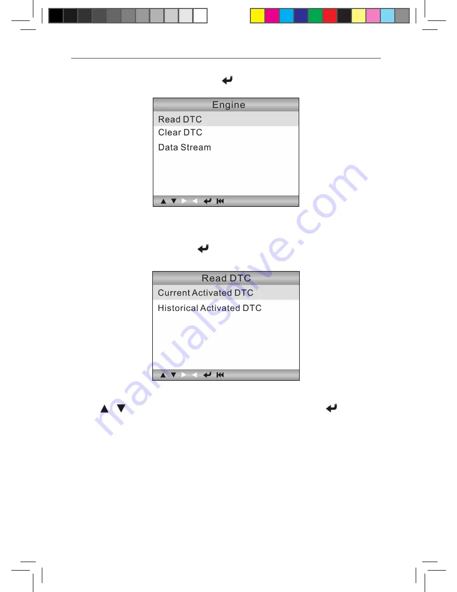
4.2.1 Read DTC

Select [Read DTC] and press [ ] in Figure 4-7, it will jump to the following 

screen:

Figure 4-8

Press [ ] [ ] button to highlight one desired item and press [ ], a screen 

similar to Figure 4-9 will appear:

Summary of Contents for CR-HD

Page 1: ......

Page 2: ...V1 00 000 2011 12 27...

Page 3: ...ny trademark service mark domain name logo or company name of LAUNCH or any third party without permission from the owner of the applicable trademark service mark domain name logo or company name You...

Page 4: ...H TECH CO LTD or its subsidiary licensing the Materials instead of LAUNCH grants to Customer a nonexclusive and nontransferable license to use for Customer s internal business purposes the Materials a...

Page 5: ...wise make available trade secrets contained within the Materials in any form to any third party without the prior written consent of LAUNCH Customer shall implement reasonable security measures to pro...

Page 6: ...main effective until terminated Customer may terminate this Agreement and the license at any time by destroying all copies of Materials and any Document Customer s rights under this Agreement will ter...

Page 7: ...or alterations to this unit or failure to strictly comply with LAUNCH operating and maintenance instructions LAUNCH shall not be liable for any damages or problems arising from the use of any options...

Page 8: ...Keep a fire extinguisher suitable for gasoline chemical electrical fires nearby Don t connect or disconnect any test equipment while the ignition is on or the engine is running Keep the CR HD dry cle...

Page 9: ...ation 1 2 1 About DTC 1 2 2 J1708 J1587 J1939 1 3 Product Descriptions 3 3 1 Outline of CR HD 3 3 2 Specifications 4 3 3 Accessories Included 4 3 4 Power supply 5 4 OPERATION 5 4 1 Connection 5 4 2 Di...

Page 10: ...ou with a guide as to where a fault might be occurring within a vehicle This section explains the basic elements of fault codes for J1587 J1708 and J1939 data bus protocols how to view these codes on...

Page 11: ...transport and application layers with respect to the OSI model SAE J1587 is used in conjunction with SAE J1708 for automobile communication SAE J1939 SAE J1939 is the vehicle bus standard used for com...

Page 12: ...r s Manual 3 3 Product Descriptions 3 1 Outline of CR HD C D Figure 3 1 No Name Descriptions Cable with OBD II CONNECTOR Connects the CR HD to the vehicle s Data Link Connector DLC LCD DISPLAY Indicat...

Page 13: ...adaptor For vehicles with 6 PIN DLC Connect 16 pin terminal of the adaptor to OBD II connector and other end to the vehicle s DLC D 9 PIN DLC adaptor For vehicles with 9 PIN DLC Connect 16 pin termin...

Page 14: ...nnect the other end to the heavy duty vehicle s DLC 4 OPERATION 4 1 Connection Turn the ignition off 111 Locate the heavy duty vehicle s Data Link Connector DLC 222 Select the desired diagnostic adapt...

Page 15: ...e Figure 4 2 A Selecting SAE J1708 6 PIN Deutsch Use button to select 6 PIN Deutsch and press a screen similar to Figure 4 3 will appear Figure 4 3 Select one desired item and press the system will sw...

Page 16: ...User s Manual 7 Figure 4 4 Press button to highlight SAE J1587 1708 and press the following screen will appear Figure 4 5 If SAE J939 is selected in Figure 4 4 press the screen will appear as follows...

Page 17: ...m item press the screen will appear as below Figure 4 7 4 2 1 Read DTC Select Read DTC and press in Figure 4 7 it will jump to the following screen Figure 4 8 Press button to highlight one desired ite...

Page 18: ...es the occurence times of the current DTC Whereas if we choose SAE J1587 1708 the faults code will be displayed similar to Figure 4 10 Subsystem Identifier SID Indicates what function on the ECU has f...

Page 19: ...re 4 11 Select one desired item and press a prompt message will appear on the screen as shown in Figure 4 12 Figure 4 12 Press to erase DTCs and if successfully Succeed will be shown on the screen Pre...

Page 20: ...d retrieve codes again If there are still some trouble codes in the system please troubleshoot the code using a factory diagnosis guide then clear the code and recheck 4 2 3 Data Stream Press button t...

Page 21: ...return to the Data Stream menu screen 4 2 3 2 Select Items Use button to select Select Items in Figure 4 14 and press a screen similar to Figure 4 16 will appear Figure 4 16 Press button to select dat...

Page 22: ...8 See Figure 4 18 shown as above 4 2 3 3 View Graphic Items Press button to select View Graphic Items in Figure 4 14 and press the system will enter the datastream selection interface Select one desir...

Page 23: ...gure 4 21 1 Beeper Turn ON OFF the Beeper Select Beeper in the main menu and press to switch to the screen shown as below Figure 4 22 The icon will appear at bottom of the screen if Beeper is set to O...

Page 24: ...s press to move the highlight bar to different position press to confirm Press to return to the Tool setup menu screen 4 4 Help This function is used to view Tool Information Figure 4 24 Tool Informat...

Page 25: ...LAUNCH CR HD User s Manual 16 5 Upgrading 5 1 CR HD upgrading flow...

Page 26: ...program of CR HD 5 3 Upgrading Log on to www crecorder com download the latest version of the CR HD upgrade package and decompress the software to local disk Connect the CR HD to computer through USB...

Page 27: ...uestion Screen of main unit flashes at engine ignition start Answer Caused by electromagnetic disturbing and this is normal phenomenon Question There is no response when communicating with on board co...

Page 28: ...e is repair or replacement and LAUNCH shall not be liable for any consequential or incidental damages Final determination of defects shall be made by LAUNCH in accordance with procedures established b...

Page 29: ......

Reviews: