


8
When possible, install the water lines at the same level as the chiller until reaching the application The height
difference between the chiller and the application should never exceed 10m (33 feet).
In the installations in
which the water level of the circuit exceeds the maximum level of the tank inside the Ultracool unit, it will be
necessary to install a check valve in the water outlet of the Ultracool unit and a solenoid valve in the water
inlet.
The power supply of this solenoid valve will be carried out by terminals 25 and 26 designed for that
purpose, see point 2.6.
To prevent rusting of the water pipes, we recommend plastic, rubber or stainless steel pipes and brass fittings.
Where flexible tubing is used, it should be of reinforced construction and rated for a minimum working
pressure of 6 bar g (90 psig) within -15ºC and 40ºC (5ºF and 104ºF).
2.6
ELECTRICAL CONNECTION
Operating voltage /-10%, 50Hz, 3 Ph or /-10%, 60Hz, 3 Ph. In terms of
Electromagnetic emissions and immunity, this unit is intended for installation in an industrial environment.
Make sure that the supply voltage does not exceed a maximum variation of 10% referring to nominal.
This unit integrates a frequency inverter with a leakage current that exceeds 3,5 mA. On installations where
a Residual Current Device (RCD) is used for extra protection, use only an RCD of Type B (time delayed).
The use of RCDs must always follow national and local regulations.
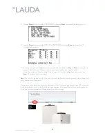
Introduce the main power supply cable through the cable gland located on the base of the chiller and connect
it to the incoming power terminals which are located on the left side of the X1 terminal block inside the
electrical box of the chiller:
For the electrical supply of the Ultracool unit, use an appropriate electrical line according to the data in the
characteristics plate.
Take the cable for the external controller display out of the chiller through the brush gland on the base of the
chiller and connect it to the back of the display.


