background image


116 / 137 

Proline Kryomats 

03/2022 


9.3.4.2.2


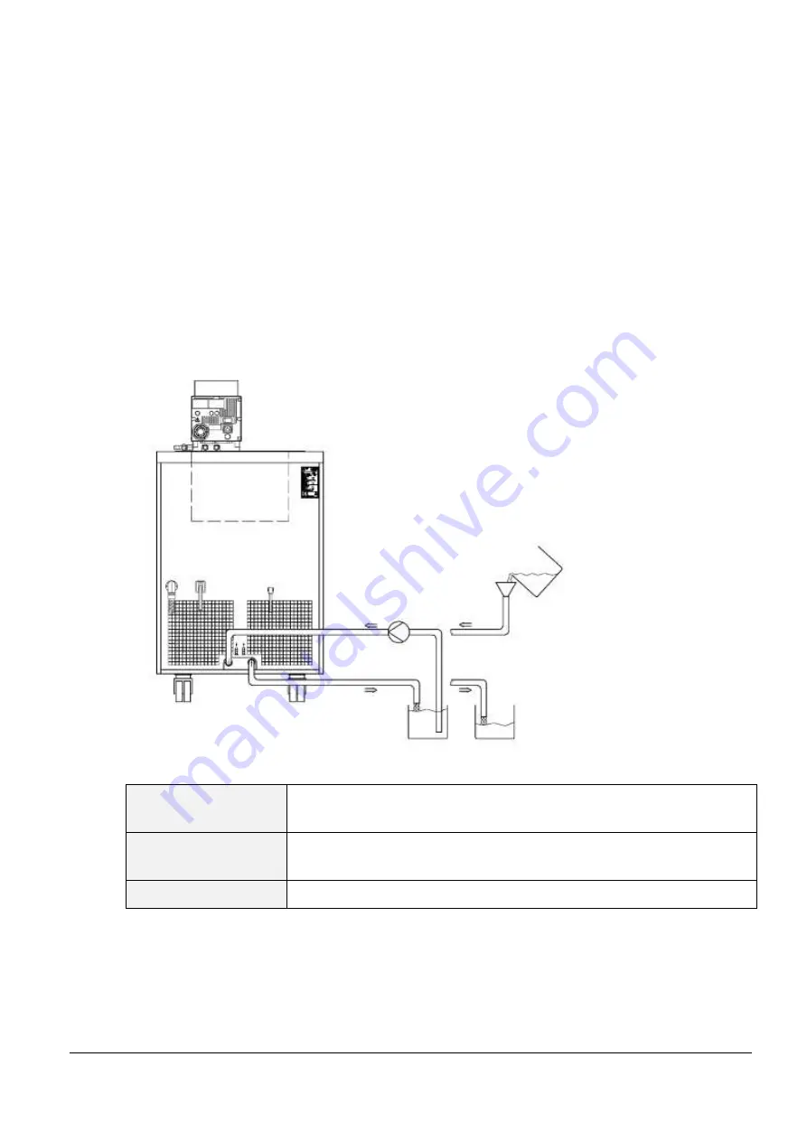
Decalcifying the water cooling circuit 

At regular intervals of 3 months or longer, the water-cooled condenser must be decalcified or cleaned. This depends 
on the hardness of the cooling water and the degree of soiling. Drain according to (

 9.2.2). 

Required equipment: 


Two containers of approx. 10 to 20 liters volume. 


Use a suitable pump (drum pump) or a hose with funnel. Place the funnel as high as possible so that the 
device can fill quickly. 


Fit connecting hoses between container, pump, cooling water inlet and between cooling water outlet 
and back to container. 


Change containers when top 
one is empty. 


Acting time: 

Continue the pump stage until most of the foamy reaction, usually at the start, has 
decayed. Generally, this is achieved after about 15 to 30 minutes. 

Decalcifier: 

Water with LAUDA Decalcifier LZB 126.  
It is essential to follow the safety instructions when handling the chemicals. 

Flushing: 

Allow at least 30 liters of water to flow through. 

9.3.5


Repair information 

If you need to send in a unit for repair, it is essential to first contact the LAUDA Service (

 9.5)


When sending in the unit, ensure that it is carefully and properly packed. LAUDA cannot be 
held liable for any damage caused by improper packing. 

Standard & Alternative 

Summary of Contents for RP 3090 C

Page 1: ...ration manual PROLINE Kryomats Low temperature thermostats with SmartCool System RP 4050 C RP 4050 CW RP 3090 C RP 3090 CW RP 4090 C RP 4090 CW Release 03 2022 j Read the instructions before starting work ...

Page 2: ...aces release 08 2020 i 11 2018 e 10 2018 d 05 2016 b2 03 13 01 09 06 08 Valid from software control system Master version 2 13 software safety system Master version 2 07 software operating system Command version 3 45 software chilling system version 2 13 software analog IO module version 3 14 software serial IO module version 3 22 software digital IO module version 3 14 software solenoid valve ver...

Page 3: ...pair moving the equipment Transport the equipment with care The unit may NEVER be overturned nor put upside down Equipment and its internal parts can be damaged by dropping by shock Technically qualified personnel must only operate the equipment Never operate the equipment without the heat transfer liquid Do not start up the equipment if it is damaged or leaking cable not only supply cable is dama...

Page 4: ... MODULES ACCESSORIES 20 4 9 REFRIGERATING UNIT 21 4 10 AVOIDANCE OF DEWING 21 4 11 HEATER RATING AND POWER CONSUMPTION FROM THE MAINS 21 5 UNPACKING 22 5 1 AFTER UNPACKING 22 5 2 STANDARD ACCESSORIES 23 5 3 PACKING AND UNPACKING WITH ORIGINAL PACKAGING MATERIAL 23 5 3 1 Background 23 5 3 2 Requirements 23 5 3 3 Unpacking the device 24 5 3 3 1 Outer cardboard box 24 5 3 3 2 Lift device from the pal...

Page 5: ...the offset of the external temperature probe 64 7 6 9 Restoring the works setting of the external temperature probe offset 64 7 7 GRAPHICAL DISPLAY OF TEMPERATURE MEASUREMENTS 65 7 8 PROGRAMMER 67 7 8 1 Program example 67 7 8 2 Selecting and starting the program Start Hold Stop 69 7 8 3 Interrupting continuing or terminating the program Hold Continue Stop 70 7 8 4 Creating or modifying a program E...

Page 6: ...ONTACT MODULE 108 8 5 1 Contact module LRZ 915 with three inputs and three outputs 108 8 5 2 Namur Contact module LRZ 914 with only one input and one output 109 9 MAINTENANCE 110 9 1 DEVICE STATUS 110 9 1 1 Interrogating the device type 110 9 1 2 Software version 110 9 1 3 Serial numbers 110 9 1 4 Device data 110 9 1 5 Fault memory 111 9 2 CLEANING 111 9 2 1 Cleaning the surface of the device 111 ...

Page 7: ...22 Proline Kryomats 7 137 9 5 HELP DESK AND ORDERING REPLACEMENT PARTS 119 10 ACCESSORIES 120 11 TECHNICAL DATA AND DIAGRAMS 121 12 DECLARATION OF CONFORMITY AND PRODUCT RETURNS DECLARATION 130 13 INDEX 132 ...

Page 8: ...equences of non compliance Action 1 Action WARNING indicates a possible dangerous situation which if the safety requirements are ignored may result in fatal or severe irreversible injuries Caution Type and source Consequences of non compliance Action 1 Action CAUTION indicates a possible dangerous situation which if the safety requirements are ignored may result in slight reversible injuries Notic...

Page 9: ...ble 2 Industrial in accordance with DIN EN 61326 1 Emissions Class B in accordance with CISPR 11 Only for EU Domestic connection value 100 A Proline Kryomat Table 2 Industrial in accordance with DIN EN 61326 1 Emissions Class B in accordance with CISPR 11 Worldwide No limitation Only for the USA Instructions for Class A digital devices This equipment has been tested and found to comply with the li...

Page 10: ... a thermal transfer liquid for temperatures above 100 C carefully remove all water residues including from the hoses and loads When doing this also open the blanking caps of the pump outputs and inputs and blow compressed air through all the pump outputs and inputs Danger of scald due to delay in boiling Withdraw the mains plug before cleaning maintenance or moving the thermostat Specialist person...

Page 11: ...DIN EN 61010 2 010 Take care of the level of the heat transfer liquid 6 2 3 Compare the information on the rating label with the supply details 4 Connect the unit only to a socket with a protective earth PE connection 5 Check whether the switch at the back of the master control element is in the ON position 6 Check whether the switch at the front of the master control element is in the ON l positi...

Page 12: ...XT End End C Control parameters setpoint resolution setpoint source input calibration etc Protection system Command cooling system analog module RS 232 module and digital module etc Display flashes Set setpoint with or Display is accepted after 4 sec or proceed immediately with the key 2 1 Menu structure Master These settings and configurations can be entered more easily and in a more clear manner...

Page 13: ...ntrast intern Pt100 extern Pt100 Device type Software Version Serial numbers Device data Error store Mode Baud rate RS 485 address internal external Pt100 Analog interface RS 232 485 Calibration Default Alarm Warning all default Basic window Standard window Super window Edit Default T il min T ih max Xp Tn Tv auto Td auto Kpe Tne Tve auto Tde auto Xpf Prop_E a Automatic Manual Status Setpoint Iden...

Page 14: ... illustration on this page 4 Bath cover 5 Rotary switch for power supply 6 Grille on both sides 7 Front cover closed 8 Four steering transport rollers two off them with stoppers 1 Pump connection on the side Pump outflow pressure output closed off with screw 2 Bypass valve in external position 3 Pump connection on the side Suction nozzle return to bath closed off with screw plug ...

Page 15: ...in tap 2 Bath drain nozzle 1 Bath edge heating and bath bridge heating 2 Nameplate 3 Mains cable 4 Connection cable for control head 5 Connection cable LiBus for control head 6 Connection bath bridge heating 7 Cooling water connections at water cooled devices W only connections as per pictogram ...

Page 16: ...et LiBus LAUDA internal bus for bus suitable for unit and to which the refrigerating lower section and Command remote control are connected 5 Mains switch 6 Connection socket 51H 7 Air intake for electronic head 8 Pump connection rear and on the side Suction nozzle return to bath pump outflow or pressure output refer to housing for label 9 Mains connecting lead 10 Rear pump connections ...

Page 17: ...ignal red LED is blinking 9 Overtemperature set point to check or set Tmax 10 Mains On green LED is lit Control element Command 1 Graphical display 2 RS 232 485 socket hidden on the back of Command 3 Cursor keys 4 Enter key 5 Standby key brings the thermostat into the idle mode Heater refrigerating machine and pump are switched off yellow LED is lit 6 Escape key to quit a window without any change...

Page 18: ...able drive pump level 5 to 8 The pump power can therefore be optimally matched to the relevant task In order to achieve optimum temperature homogeneity in the heat transfer liquid in the bath it is recommended to select the pump level in dependence of the viscosity of the heat transfer liquid therefore at higher viscosity to increase the pump level Be cautious at higher bath levels to avoid liquid...

Page 19: ...re in the bath A high resolution A D converter processes the measurement Further measurement conditioning occurs using a special control algorithm for controlling the heater actuator which has a low reactive effect on the mains and the SmartCool refrigeration equipment together with further transducers An external Pt100 temperature probe can be connected via a socket 10S for the acquisition of an ...

Page 20: ...Interfaces The device is equipped in series with the following sockets One socket 10S for the connection of an external Pt100 temperature probe Two sockets 70S for the connection of components via the LAUDA equipment bus cooling section Command remote control external solenoid valve etc An RS 232 485 interface 65S at the back of the Command remote control 4 8 Interface modules accessories The Mast...

Page 21: ...ots must not be restricted respectively covered 6 1 The Proline Kryomats are equipped with the SmartCool technology which makes optimum use of the compressor and only then cools when refrigerating capacity is demanded by the controller To achieve this a number of sensors in the cooling circuit monitor the operating conditions The compressors are equipped with overtemperature cutouts which respond ...

Page 22: ...n a level surface Observe the packing instructions Notice Falling toppling equipment Property damage Do not tilt the cooling device during transport and never turn it upside down To repack the unit carefully and properly it is necessary to store the original package 5 1 After unpacking After unpacking first check the device and accessories for any damage in transit If contrary to expectations ther...

Page 23: ... Screw plugs for M16 x 1 already mounted for all Kryomats EOA 001 2 Threaded house coupling Nipple Nut G for water cooled devices only EZB 260 1 Warning label Hot surface for all Kryomats 5 3 Packing and unpacking with original packaging material 5 3 1 Background For the customer to allow a properly packaging e g for further transport or return transport to LAUDA To repack the unit carefully and p...

Page 24: ...2022 5 3 3 Unpacking the device 5 3 3 1 Outer cardboard box Open the cardboard box on top Pallet Take out the filling material and the accessory parts Draw out the four nails on the edge which fix the cardboard box on the pallet ...

Page 25: ...ve the outer cardboard box vertically upwards 5 3 3 2 Lift device from the pallet Two textile round slings Attention The round slings must not press against the structure of the device Pay attention to the center of gravity of the device ...

Page 26: ... device length Textile round slings 5 3 4 Repacking with original packing material The packaging of a device takes place in the reverse order 5 4 In plant transport with hand pellet truck or fork lifter The Proline Kryomats can only be positioned diagonally on the conveyor fork ...

Page 27: ...ats 27 137 Transport the device on a hand pellet truck Transport the device with a fork lifter 5 5 Before preparation Remove the protective foil For installation and commissioning the operating instructions must be observed ...

Page 28: ...n the device Crushing of the hands and feet Do not place any heavy parts on the device Caution Contact with hot cold heat transfer liquid Scalds frost bite Bring the heat transfer liquid to room temperature before draining Drain the heat transfer liquid before transportation Disconnect the device from the mains If necessary disassemble accessories Caution Skin contact with hot cold surfaces Burns ...

Page 29: ...e Master control element and secure it Operation with external loads Circulating thermostat continue at 0 Check whether the pump connectors at the side and back are fitted with sealing caps 3 or that hoses are fitted for external loads Using bath temperatures over 70 C the supplied self adhesive label should be applied on the bath at an easily visible point Do not carry out technical changes on th...

Page 30: ...isplay of the warning WXArn103 7 12 4 Changes in volume of the heat transfer liquid during temperature changes should be taken into account Best operation is with a level 30 80 mm below the top edge of the bath The cooling pipe of the evaporator should be covered Low level cut off occurs at about 95 mm below the top edge of the bath The units are designed for use with non flammable and flammable l...

Page 31: ...he mains switch rotary switch withdraw the mains plug The drain tap 1 is located behind the front panel Fit the hose onto the draining nozzle 2 Open the drain tap and run off the heat transfer liquid Close the drain tap Follow the regulations for the disposal of used heat transfer liquids 6 3 Connection of the cooling water Note that the following conditions apply for the connection of the cooling...

Page 32: ...ZB 214 LZB 314 Therm 250 50 250 Silicone oil 130 45 at 50 C 300 LZB 122 LZB 222 LZB 322 At higher temperatures Evaporation losses Use bath covers Only use distilled water or fully demineralized high purity water after adding 0 1 g of soda Na2CO3 sodium carbonate liter of water Risk of corrosion Water content falls with longer operation at high temperatures Mixture becomes flammable flash point 119...

Page 33: ...rantee Important Danger of corrosion of the cooling water circuit due to water of unsuitable quality Free chlorine e g from disinfectants and water containing chlorine lead to pitting in the cooling water circuit Distilled deionized or demineralized water is unsuitable due to its corrosive properties and leads to corrosion in the cooling water circuit Seawater is unsuitable due to its corrosive pr...

Page 34: ...lution due to leakage To avoid pollution due to a leak in the cooling water system it is recommended that a leakage water detector with a water cut off is installed Servicing intervals Follow the information for cleaning and decalcifying the cooling water circuit 9 3 4 2 c Hoses Elastomer hoses Hose type Internal width Ø mm Temperature range C Field of application Order number EPDM hose uninsulate...

Page 35: ... hazard from leaking heat transfer liquid Fit sealing plugs to the pump connections when no external consumers are connected and set the flow distribution to internal INT Operation as circulating thermostat Caution Bursting of the external consumer due to overpressure Scalding frostbite cutting Use a pressure relief device on pressure sensitive consumers e g glass reactors When used as circulation...

Page 36: ...ening the union nuts on the pump nipple AF 19 use a wrench AF 14 to counter the tightening torque see figure If external control is to be used provide a Pt100 temperature probe in the external load 7 5 2 and 7 5 4 With loads at a higher position and with stationary pump and ingress of air into the thermostatic circuit the external volume can drain away even with closed circuits Risk of thermostat ...

Page 37: ...with a hydrometer Warning Risk of heat transfer liquid overheating due to incorrect entry of overtemperature switch off point Tmax Fire The overtemperature switch off point must be below the flash point of the heat transfer liquid Set the overtemperature switch off point Tmax to 5 K above the upper limit of the temperature range for your application Warning Bursting of the external consumer due to...

Page 38: ...ontact with vapors from the heat transfer liquid Harmful by inhalation Use an extractor hood If possible use a bath cover Caution Bath overflow due to thermal expansion or immersion of objects Burns scalds frostbite Take the volume of external consumers into account Take into account the increase in volume with a rise in temperature Notice Inadmissible operating temperatures temperature difference...

Page 39: ... a 16 ampere circuit breaker fitted during installation Exception Devices with 13 ampere UK plugs Three phase devices For three phase devices the rating of the circuit breaker must match the power consumption of the device The value will be found on the type plate In each case select the next higher value Using an excessively high rated circuit breaker is not permissible 7 2 Switching on Check whe...

Page 40: ...eat transfer liquid this has been pumped out by filling the external load Display for LEUEL low level appears when the bath has too little liquid Red LED above the fault triangle flashes Find cause of fault and where necessary top up missing heat transfer liquid 6 3 Press the Enter key Also press the key if unit has been switched off in the fault state No release is possible on Command remote cont...

Page 41: ...ng display remains active so that status displays can be viewed and settings carried out However a started timer 7 10 continues to run Stop as required with Pause 7 4 Key functions Your Proline Thermostat is easy to operate 7 4 1 General key functions and pilot lamps Master Enter key From the actual value display at the main menu level activates input display flashes saves input display ceases to ...

Page 42: ...connected The following always applies After termination of the relevant settings they are accepted automatically after approx 4 s or the setting is accepted immediately with the Enter key and Fault signal Flashing red Alarm LED and acoustic signal An acoustic signal can only sound when it has not been intentionally deactivated 7 6 5 The bath control occurs via the external temperature probe when ...

Page 43: ...ke to change the setpoint temperature then press the duo key under Tset Brightness Contrast The brightness and contrast can be set on the Command remote control The works setting can be changed via Settings Basic settings Display Brightness or Contrast The brightness of the LCD illumination can be selected from eight steps or switched off completely The contrast can be set in eight steps Screen Th...

Page 44: ... normal super and graphics recorder windows Tset Changes setpoint temperature Tfix Calling and setting of saved setpoints 2 Standard window with five important items of information Tint current bath temperature Tset setpoint Text current temperature on external probe if connected Level of heat transfer liquid in cm above the minimum level Pump level of the Varioflex pump Soft keys like above Pump ...

Page 45: ... shown graphically against time 7 7 Soft keys like above 7 4 2 Changing window information Command Display data You can adapt the information displayed by your Command remote control to your requirements For example if you have not connected any temperature probe you can exchange it in the standard setting of the normal window for the maximum temperature Tmax safety cut off This is how it is done ...

Page 46: ...dvantageous when the thermostat is positioned in another room and the Command remote control is used as a remote control device Then the Master keyboard can be locked to prevent unintentional adjustment Master SAFE Locking and hold pressed simultane ously for 3 s SEtappears for 3 seconds then the segments of the first right hand 0are formed hold both keys pressed until this display is completely v...

Page 47: ... pressed simultaneously for three seconds The locking window appears Hold both keys pressed until the progress bar is completely filled Then the display skips back to the previously set Screen mode The soft key boxes are now blank indicating that the keyboard is locked On pressing any Master key the display appears Keyboard locked Unlocking Press and then and hold pressed simultaneously for three ...

Page 48: ...Wait 4 seconds or Display flashes 4 seconds new value is automatically accepted or value is accepted immediately with Enter key For safety reasons the setpoint can only be set up to 2 C above upper limit of the operating temperature range for the relevant device type In the following cases the manual setpoint entry is blocked Setpoint is taken from the analog module from the programmer in the Comm...

Page 49: ...th or Confirm the value with or quit the window with without having made any changes Two other ways of entering the setpoint With the soft key Tfix open the window shown on the left The setpoints which you last entered are shown in the right hand column In the illustrated screen the last setpoint was 80 0 C To accept an earlier setpoint enter the right hand column with and select the desired value...

Page 50: ... can be used as the controlled variable for the bath temperature in applications with a noticeable temperature gradient between the internal bath temperature and an external load The setup is described in Section 7 5 4 With the function described in the following you only change over the display External actual temperatures can also be read in by interface modules 8 Connection of the external Pt10...

Page 51: ... modules 8 7 5 3 Setting pump power or standby With the Proline Varioflex pump four pump levels level five till level eight are available with which the bath circulation flow rate and pressure the noise generated and the mechanical heat input can be optimized Pump level eight gives the best bath circulation and temperature homogeneity Master Pu and 1 x Call pump power levels display Pu The current...

Page 52: ...dow with without making any changes It is not possible to select the pump levels 1 to 4 Standby activation Standby activation Pump heater and refrigerating machine are deactivated when the green LED in the lower part of the key is lit Please exercise caution when thermostat is in standby mode The following settings actions may start the thermostat unintentionally from standby mode A previously act...

Page 53: ...any changes Automatic mode means that the external pump is switched off while the unit is in standby mode or it is switched on while the unit is running 7 5 5 Activating external control An external temperature probe can be connected to the Proline Thermostats How this is done is explained in Section 7 5 2 If the bath temperature is to be controlled using this sensor instead of the internal sensor...

Page 54: ...source 1for the internal probe EPonly when an external probe is connected EAonly when an analog module is connected and configured ESonly when a serial module is connected and is continuously receiving actual values from a PC Wait 4 seconds or Display flashes 4 s new value is automatically accepted or value is immediately accepted with Enter key If EP EAor EShas been selected then the green LED in...

Page 55: ...a the soft key Menu With the cursor keys change further to Settings Basic settings Current Consumpt 16 0 A is active Open the settings window with Changes are not accepted Quit the window with Pump Menu End Tset Tfix 16 0 A Display Sounds Master Sounds Command Language Master Mode Autostart Current consumpt Help Menu Screen Tset Tfix 6 7 8 9 0 1 2 3 4 5 Max current consumption in A 16 0 Min 10 0 A...

Page 56: ...h Change the time with cursor or soft keys and accept with or quit the window with without making changes The date is set just the same with Set date The date format Day Month Year or Month Day Year can be set under Format of date Help Menu Screen Tset Tfix 6 7 8 9 0 1 2 3 4 5 Enter time 15 38 12 Pump Menu End Tset Tfix Set time Set date Timer 1 Timer 2 Format of date Pump Settings Graph Clock Pro...

Page 57: ...t key Menu With the cursor keys continue to Settings Display resolution Select the desired resolution with or Accept selection with or End or quit the window with without making any changes Pump Menu End Tset Tfix Calibration Works settings Resolution Device status Display data Basic settings Overlevel handling Pump Settings Graph Clock Programmer Interfaces Control Limits Pump Menu End Tset Tfix ...

Page 58: ...tart Open the device parameter menu via the soft key Menu With the cursor keys continue to Settings Basic settings Auto start On is currently active If the standby mode is to be activated after a mains interruption activate Off with or Accept the change with or End or quit the window with without making changes When the mains voltage has been restored after an interruption you can quit the standby...

Page 59: ...s the maximum temperature and 5 C as the minimum temperature Command Limits Open the device parameter menu via the soft key Menu With the cursor keys continue to Limits The minimum and maximum temperatures are displayed T il min is currently active Select the limit to be changed with or and confirm with Enter the desired limit temperature Accept the change with or quit the window with without maki...

Page 60: ...ys continue to Control Setpoint offset Offset source Off indicates that the setpoint offset is currently deactivated Select the setpoint source with or and confirm with Interfaces e g RS 232 are only displayed if a valid setpoint has already been transmitted With the cursor keys continue to Setpoint offset The standard value is 0 00 C Open the left hand window with Enter the desired temperature Ac...

Page 61: ...works setting with all default Under Master you have the choice between all default then all Master settings are reset only control para int for the internal control parameters only control para ext similar for external only miscellaneous which resets setpoint pump level maximum current consumption control to internal and auto start to Auto Under Command all command settings are reset with All def...

Page 62: ...tering the offset of the internal temperature probe If during checking with a calibrated reference thermometer a deviation is found then the offset i e the additive part of the characteristic of the internal measuring chain can be adjusted with the following function The reference thermometer must be dipped into the bath according to the details on the calibration certificate Command Calibration O...

Page 63: ...ionally the works setting can be restored with this function Command Default Open the device parameter menu via the soft key Menu With the cursor keys continue to Settings Calibration intern Pt100 Default The window shown adjacent appears Confirm selection with Confirm the control dialog on the right with or cancel with Return to the measurement window with End or Help Menu Screen Tset Tfix 6 7 8 ...

Page 64: ...keys continue to Settings Calibration extern Pt100 Calibration The adjacent window appears Confirm selection with Continue as described in 7 6 6 for the internal temperature probe 7 6 9 Restoring the works setting of the external temperature probe offset If the offset has been misadjusted unintentionally the works setting can be restored with this function Command Default Open the device parameter...

Page 65: ...l is to be invisible or visible Sample time defines with which time interval the measurements are recorded 5 possibilities are offered From 2s max 1h45min up to 2min max 105h Time axis defines over which time range the measurements are to be displayed With Automatic the program finds the optimum display Manual input from 9min up to 144h Time base defines whether scaling is to be carried out With R...

Page 66: ...nter the desired new value in the changes window in the usual way When setting the minimum value the largest permissible value here 26 90 C since the maximum value is 27 C is stated When setting the maximum value it is conversely the minimum value which is entered However if a value is entered which exceeds the other corresponding limit then this warning is issued Warning Value not in input range ...

Page 67: ...ribed by the target temperature i e the temperature at the end of the segment and the duration from the start to the end of the segment Step Without any specified time the final temperature is approached as quickly as possible Temperature hold phase No temperature change i e the temperatures at the start and end of a segment are the same The programmer can be controlled or changed via the RS 232 i...

Page 68: ...ection 0 The field tolerance refer to the above program table and the graph below It facilitates exact conformance to the dwell time at a specified temperature Segment 1 is not processed until the bath temperature is within the tolerance range so that the ramp Segment 2 starts delayed at A tolerance range which is too tight can however also cause undesired delays In particular with external contro...

Page 69: ...ubmenu Status appears Using the Status menu the selected program can be 1 started Start 2 paused Hold 3 continued Continue or 4 terminated Stop In addition the standby key stops the programmer Pause operation After standby is deactivated the programmer goes on Commands which depending on the situation cannot be executed are not displayed Continue therefore only appears when Hold has been activated...

Page 70: ...or Stop are shown Here with the aid of the keys or and the running program can be paused with Hold or terminated with Stop Once the program has been terminated the device runs with the last setpoint setting Continuation of a program paused with Hold occurs using Continue which is obtained with Pump Menu End Prog 1 running Status Edit Loops Graph Info Hold Stop Pump Menu End Prog 1running Status Ed...

Page 71: ...eletion of a segment In addition when a program has just been executed new segments can be inserted and existing ones modified even the currently active segment Furthermore all segments except the currently active one can be deleted at any time Modifications to the currently running segment are possible The segment then continues as though the modification had been applicable since the start of th...

Page 72: ...change It can be edited by pressing the key see following pages The soft key Insert inserts in the marked line a new segment that has a default value taken from the previous segment with the exception of the Tolerance field The Tolerance is always specified as 0 00 All following segment lines will be moved one line downwards In the above window Segment 1 was created in this way Continue with to th...

Page 73: ...opied If the field in the column T end C has a black background the entry mode End of segment temperature is obtained by pressing the key Depending on the setting that is the temperature which the thermostat is to achieve on the internal or external temperature probe Enter the value confirm with the key and continue to the Time entry field with If the field in the column Time has a black backgroun...

Page 74: ...rm with Continue with to the entry field Pump If the field in the column Pump has a black background the entry mode for the Pump level is obtained by pressing the key With or select Pump Level 5 8 or and confirm with stands for no change to previous segment i e when is present in all fields the pump level always retains the start setting or the setting before the program start Continue with to the...

Page 75: ...e Contact output is obtained by pressing the key With or select Open or Closed and confirm with stands for no change with respect to the previous segment i e if is present in all fields the contact setting of the start setting or that from the program start is retained If applicable continue with to Out 2 and Out 3 Programming is terminated with or End Pump Menu End Tset Tfix Contact out open clos...

Page 76: ...ogram to repeat continuously Confirm the entry with the key and return to the display You can quit the Edit mode with or End 7 8 6 Viewing the program sequence as a graph Graph Command Programmer Program1 Graph takes you to the submenu Graph Press the key Show chart and The program sequence is shown Pump Menu End Tset Tfix Status Edit Loops Graph Info 1 Pump Menu End Tset Tfix Status Edit Loops Gr...

Page 77: ...s necessary to process step changes in temperature Number of free segments Segment which is at present currently being processed Residual time of the current segment in hours and minutes Current pass in the example the third of all passes is running The last three points are only displayed when a program runs Quit the window with or End T C Pump Menu End Tset Tfix 27 00 26 00 25 00 24 00 23 00 00 ...

Page 78: ...are attained Command Ramp function Open the list of device parameters using the soft key Menu With the cursor keys continue to Programmer Ramp function Confirm with the key Enter a positive or negative temperature value with Temp change With Time enter a figure without time unit With Time unit choose between Second s up to Day s Under Status the ramp is started Start or stopped Stop When the ramp ...

Page 79: ...in from the standby mode The menu Function is used to define when an action is executed Similar to an electronic mains timer Weekplan enables two switching events to be carried out each day The cycle is repeated after 7 days Time absolute defines a time and a date on which a once only action switching event occurs The time point is set with Set time and with Set date Time relative defines a waitin...

Page 80: ... bath thermostat with water as the bath medium with internal control The parameters are also preset for the operation of external containers with external control Sometimes however the operation of external containers requires adaptation In addition the thermal capacity and viscosity of the heat transfer liquid sometimes require adaptation The intelligent menu guidance with the Master control elem...

Page 81: ...Water 9 0 60 42 6 3 8 RP 4090 CW Ethanol 9 0 60 42 6 3 8 RP 4090 C Water 9 0 60 42 6 3 8 RP 4090 C Ethanol 9 0 60 42 6 3 8 Technical changes reserved 7 11 2 External control variable External measurement probe You only need to read further here if you have connected an external temperature probe or the actual temperature is read in from a module and you have activated it as control variable accord...

Page 82: ...ct the parameters to be changed with and confirm with Then change the value in the following settings window and confirm with Correction limitation see introduction 7 11 2 1 Steps for setting the control parameters for external control 1 Activate external control 7 5 4 2 Setting the slave controller 2 1 Set parameters to auto Check for thermostat type and change when necessary RP 9 1 1 Choose heat...

Page 83: ... oscillations with large period i e 10 min Kpe higher otherwise lower 3 2 Tne Tve Tde setting Start with high numbers Tne 70s 200s Tve 50s 150s With lower numbers faster approach otherwise slower approach with lower oscillations Tve to reduce overshot Tve higher otherwise lower Tde damping for Tve in general approximately 10 of Tve 4 Correction limitation or outflow temperature limitation 7 11 2 a...

Page 84: ... later reuse With Default the set of control parameters saved at the works is loaded again in this case the control parameters set by the customer are lost Command Control parameter sets Open the device parameter menu via the soft key Menu With the cursor keys continue to Control Control Parameters Control para sets The adjacent window appears Set 1 to Set 9 Select the desired set with and confirm...

Page 85: ...t run of the thermostat In this case the thermostat and if applicable the external application must be ready for operation 6 The Self Adaption will be performed with the actually set pump step Best results can be achieved with high pump steps The test run must be performed at a passive system this means that during the test run an exothermic or endotherrmic reaction mustn t take place The test run...

Page 86: ...scillate less than about 15 Kelvin around the set temperature Change the display in the adjacent window and accept with With the menu Identification the optimal control parameters for internal control or for the internal control and the external control can be detected automatically To detect the control parameters for the external application a temperature probe must be connected to the thermosta...

Page 87: ... parameter set 9 After the test run the detected control parameters will be taken over as control parameters automatically If the parameters found do not fulfil your expectations the before set parameters can be restored 7 11 3 Pump Menu End Tset Tfix Status Setpoint Identification Actual Parameters Store in Set 9 ...

Page 88: ...ice please give information to the LAUDA Service 9 5 Find cause of alarm or warning and rectify where necessary Then press on the Master keyboard in order to remove the alarm message Warning messages can be removed either on the Master keyboard with or on the Command board with Warnings may be ignored by pressing or on the Master keyboard or by activating the Screen Softkey on the Command remote c...

Page 89: ...s intended to prevent unintentional adjustment Set the overtemperature switch off point Tmax below the flash point of the heat transfer liquid The setting range is restricted to 5 C above the upper limit of the working temperature range Tih 7 6 2 If the bath temperature rises above the overtemperature cut off 1 Alarm sounds as dual tone signal 2 tEMNP for overtemperature appears in the display 3 T...

Page 90: ...ater switches off on both poles Varioflex pump and refrigerating unit are switched off Find the cause of the fault and where necessary top up for missing liquid 6 2 and 6 3 Press the Enter key Also press this key if the unit has been switched off in the fault state Checking the safety system at regular intervals by lowering the bath level To do this fit a hose to the drain point and slowly run off...

Page 91: ...vel goes down This is the factory setting Warning and heater off nHWXH Warning heater off Warning and additional heater off as long as the level goes down Recommended for flammable heat transfer liquids with much higher flash point and temperatures above 100 C Alarm nHALA Alarm Alarm switches off the pump and the heater until the alarm is removed by Recommended for external loads and flammable liq...

Page 92: ...es Heater switches off on both poles Pump and refrigerating unit are switched off electronically Find the cause of the fault Possible causes may be 1 Volume expansion on heating 2 Feed to an external vessel may be interrupted so that only return suction is possible 3 Heat transfer liquid taking up moisture If Alarm Press Enter key Warnings disappear automatically when the cause is gone Also press ...

Page 93: ...e Master control panel 7 12 6 Pump motor supervision Dry running The SelfCheck Assistant monitors the Varioflex pump 1 Alarm sounds as dual tone signal when the pump runs without liquid This can only occur when the float level measurement has failed 2 The display of PuLEUsignals that the SelfCheck Assistant has detected a pump low level 3 The red LED above the fault triangle flashes Heater switche...

Page 94: ...compressor has time enough to cool down again This error may affect stage 1 Error 68 or stage 2 Error 69 If the error is always present after switching on the device please give information to the LAUDA Service 9 5 7 12 8 Three phase current Command Error Three phase current Error Three phase current is shown in the display signed by number 70 The cause is the wrong direction of the current rotati...

Page 95: ... 4 tih limitation active WX104 Bath level is approaching switch off level or is out of optional range WX 5 Heatsink temperature is superheated WX105 Heater 1 break WX106 Heater 2 break WX107 Heater 3 break WX 11 Software version of protection system too old WX110 Software version of control system too old WX 12 Software version of operating system too old WX112 Software version of operating system...

Page 96: ... Software version of analogue interface too old WX215 Software version of RS 232 too old WX315 Software version of RS 232 too old WX216 Software version of contact I 0 too old WX316 Software version of contact I 0 too old WX217 Software version of valve 0 too old WX317 Software version of valve 0 too old WX218 Software version of valve 1 too old WX318 Software version of valve 1 too old WX219 Soft...

Page 97: ...9XX Message Meaning Message Meaning WX601 Overflow of CAN receipt WX701 Overflow of CAN receipt WX602 Watchdog Reset WX702 Watchdog Reset WX610 Software version of control system too old WX710 Software version of control system too old WX611 Software version of protection system too old WX711 Software version of protection system too old WX612 Software version of operation system WX712 Software ve...

Page 98: ...t the back of the master control head into two module slots Switch off the Kryomat at the rotary switch on the front panel and withdraw the mains plug Touch the earthed bath cover of the Proline thermostat to discharge any electrostatic charge Remove the module from its packaging Insert a screwdriver into the lower recess of the module cavity and prise up the plastic cover The cover can then be pu...

Page 99: ...ating signal Pump power Pump speed 2400 4800 9600 19200 Mode Baud rate RS 485 address Voltage 0 10V Current 0 20mA Current 4 20mA Status Function Interface type Minimum value Maximum value Calibration Off On Voltage 0 10V Current 0 20mA Current 4 20mA Function Contact open Contact closed Off Fault Standby Programmer Alternating mode Control type Only if setpoint temp alternating mode is active Inp...

Page 100: ...mostat to the PC use 1 1 cable and not a null modem cable without hardware handshake the computer PC must be set to the operating mode without hard ware handshake Use screened connecting cable Connect screen to connector case The connections are galvanically isolated from the rest of the electronics Any pins not in use must not be connected When a PC is connected up the RS 232 interface can easily...

Page 101: ... command This ensures that the sequencing of inquiries and answers is clear CR Carriage Return Hex 0D LF Line Feed Hex 0A Example Transfer of setpoint 30 5 C to the thermostat Computer Thermostat OUT_SP_00_30 5 CRLF OK CRLF 8 3 3 Connecting cable RS 485 Thermostat 9 pin sub D socket Pin Data 1 Data A 5 SG Signal Ground optional 6 Data B Use screened connecting cables Connect screen to connector ca...

Page 102: ...XX External temperature to be set through the interface OUT_SP_00_XXX XX Setpoint transfer with up to 3 places before the decimal point and up to 2 places behind OUT_SP_01_XXX Pump output step 1 to 8 OUT_SP_02_XXX Operation mode cooling 0 OFF 1 ON 2 AUTOMATIC OUT_SP_04_XXX X TiH outflow temperature high limit OUT_SP_05_XXX X TiL outflow temperature low limit OUT_PAR_00_XX X Setting of control para...

Page 103: ...ater cooling unit OFF RMP_SELECT_X Selection of the program 1 5 to which the further instructions apply When the unit is switched on program 5 is selected automatically RMP_START Start the programmer RMP_PAUSE Hold pause the programmer RMP_CONT Restart the programmer after pause RMP_STOP Terminate the program RMP_RESET Delete the program all Segments RMP_OUT_00_XXX XX_XXXXX_XXX XX_X Set a programm...

Page 104: ...AR_05 Read control parameter TnE 980 OFF IN_PAR_06 Read control parameter TvE 0 OFF IN_PAR_07 Read control parameter TdE IN_PAR_09 Read value of correction limitation IN_PAR_10 Read control parameter XpF IN_PAR_14 Interrogation of the setpoint offset IN_PAR_15 Read control parameter PropE IN_DI_01 State of contact input 1 0 open 1 closed IN_DI_02 State of contact input 2 0 open 1 closed IN_DI_03 S...

Page 105: ...at adjustment alarm 7 char no external control variable RMP_IN_00_XXX Read a program segment XXX response e g 030 00_010 00_005 00_001 00 set point temperature 30 00 C time 10 min tolerance 5 00 C pump level 1 RMP_IN_01 Read the current segment number RMP_IN_02 Read the set number of program runs RMP_IN_03 Read the current program run RMP_IN_04 Read the program to which further instructions apply ...

Page 106: ...5 Syntax error in value ERR_6 Illegal value ERR_8 Module ext temperature not available ERR_30 Programmer all segments occupied ERR_31 Set point not possible analogue set point input ON ERR_32 TiH TiL ERR_33 No external sensor ERR_34 Analogue value not available ERR_35 Auto is selected ERR_36 No set point input possible Programmer is running or is pausing ERR_37 No start from programmer possible an...

Page 107: ...nd Set temperature The temperature source with which active control occurs MN tC Controlled temp Actual temperature bath temperature MN t1 or Internal Temp External actual temperature from Pt100 MNtEP or Temp external Pt100 External actual temperature from analogue input MNtEA or Temp external analogue External actual temperature from the serial interface MNtES or Temp external serial Actuating si...

Page 108: ...Stb or Stand by Control programmer Input 1 activates programmer 1 input 2 activates programmer 2 etc At the first close the programmer gets starting open removes it in pause The next close initiate continue with function F Pr6 or Programmer Control alternating mode the switching state contact open or closed allot to two different setpoint temperatures F t2C or alternating mode Controller mode the ...

Page 109: ...t and one input on each of two DIN sockets Contact inputs and outputs Output Input View on flange plug Front or solder side coupler socket Max 30 V 0 2 A Coupler socket Catalogue number EQD 047 View on flange plug Front or solder side coupler socket Signal circa 5 V 10 mA Do not use pin 3 Coupling plug Catalogue number EQS 048 1 n o make 2 common 3 n c break Use shielded lines Connect shielding wi...

Page 110: ...isplayed 9 1 4 Device data Command Device data Settings Device status Device data Display Text shows various actual temperatures in C from ext Pt100 and the modules T cont head and T heatsink are temperatures of electronics in the Master in C Pump power in Watts speed in rpm current in ampere A Tint indicates the current internal bath temperature in C Mains voltage in percentage of nominal and fre...

Page 111: ...zard Disconnect the device from the mains before cleaning Notice Live parts in contact with cleaning agents Property damage Disconnect the device from the mains before cleaning Water and other liquids must not enter the control head Cleaning can be carried out with water to which a few drops of surfactant washing up liquid have been added and using a damp cloth Carry out appropriate decontaminatio...

Page 112: ...r the water The display changes automatically to the overview window To close the valve again selects this menu again The item is called now End unfill conden 9 3 Servicing cleaning repair and disposal information Warning Live parts during troubleshooting Electric shock hazard Disconnect the device from the mains before the repair e g when changing components Have the repair carried out only by a ...

Page 113: ...ied out only by a specialist 9 3 1 Servicing LAUDA Thermostats largely require no service If the heat transfer liquid becomes contaminated it should be replaced 6 2 At the back of the Master head a main fuse switch is located which interrupts the mains connection when an overload occurs It is then in the O position and can be set in the position again If the fuse trips again Service must locate th...

Page 114: ...ature protection Quarterly 7 12 1 Low level alarm warning Quarterly 7 12 2 9 3 3 Testing the heat transfer liquid Caution Contact with hot cold heat transfer liquid Scalds frostbite Bring the heat transfer liquid to room temperature for analysis If required the heat transfer liquid should be checked for fitness for use e g when changing the method of operation or at least half yearly Further use o...

Page 115: ...f dust at intervals of one month or longer depending on the operating period and dust level in the ambient air To do this open the front grille brush off the condenser and where necessary blow over with compressed air Extreme contamination is detected by the Proline SelfCheck Assistant which then issues a warning 9 3 4 2 Water cooled condenser 9 3 4 2 1 Cleaning the dirt trap At regular intervals ...

Page 116: ...er inlet and between cooling water outlet and back to container Change containers when top one is empty Acting time Continue the pump stage until most of the foamy reaction usually at the start has decayed Generally this is achieved after about 15 to 30 minutes Decalcifier Water with LAUDA Decalcifier LZB 126 It is essential to follow the safety instructions when handling the chemicals Flushing Al...

Page 117: ...vertemperature cut off point or set the cut off point higher than the outflow temperature Master Warning message WXArn 104 Command Level very low Imminent low level in the bath vessel Master Alarm message LEUEL Command Low level Low level in the bath vessel 7 12 2 1 Check hoses connections and load for whether a leaky location is present As applicable rectify the leakage and top up the missing hea...

Page 118: ...ror 11 Command Overpressure outflow pressure too high Pump level too high Select a lower pump level 7 5 3 Compressor overtemperature 7 12 7 Three phase current 7 12 8 9 4 Disposal information The following applies for EU member states The device must be disposed of according to Directive 2012 19 EU WEEE Waste of Electrical and Electronic Equipment 9 4 1 Disposal of the refrigerant Caution Uncontro...

Page 119: ...trument type and serial number from the nameplate This avoids queries and supply of incorrect items Nameplate Your contact for service and support LAUDA Service Telephone 49 0 9343 503 350 English and German Fax 49 0 9343 503 283 E mail service lauda de We are available any time for your queries and suggestions LAUDA DR R WOBSER GMBH CO KG Laudaplatz 1 97922 Lauda Königshofen Germany Telefone 49 0...

Page 120: ...apter cable for the LAUDA internal bus LiBus For the connection of further LiBus components with heating thermostats two LiBus connections are not occupied and one with cooling thermostats EKS 073 Extension for LiBus 5m For LiBus components but especially for remote operation with the Command remote control EKS 068 Extension for LiBus 25m EKS 069 Automatic refill device with LiBus control Evaporat...

Page 121: ... Master 0 01 Command 0 1 0 01 0 001 Display accuracy 0 2 C can be calibrated additively Section 1 3 last Point Temperature stability 10 C with ethanol K 0 05 Safety equipment Class III FL suitable for flammable and non flammable liquids Cooling Air Water Ccooling water consumption temperature 15 C pressure 3 bar L h 700 Water cooling connections DIN EN 10226 1 inch G Heater power 400 V kW maximum ...

Page 122: ... L 32 44 Bath opening B x L mm 350 x 350 Bath depth usable depth mm 250 230 Height to top of bath mm 905 Overall dims B x L mm 600 x 700 Overall dim H mm 1160 Weight kg 130 Power consumption 400 V kW 5 0 Power consumption 208 V kW 5 0 Power consumption 200 V kW 5 0 Ingress protection rating IP Code accord to IEC 60529 IP 2 1 Protection class Protection class 1 according to DIN EN 61140 VDE 0140 1 ...

Page 123: ... be calibrated additively Section 1 3 last Point Temperature stability 10 C with ethanol K 0 05 Safety equipment Class III FL suitable for flammable and non flammable liquids Cooling Air Water Air Water Cooling water consumption temperature 15 C pressure 3 bar L h 700 700 Water cooling connections DIN EN 10226 1 inch G G Heater power 400 V kW maximum 3 5 Heater power 208 V kW maximum 3 0 Heater po...

Page 124: ... x 1 olives 13 mm external diameter Bath volume from to L 23 31 32 44 Bath opening B x L mm 350 x 200 350 x 350 Bath depth usable depth mm 250 230 Height to top of bath mm 905 Overall dims B x L mm 600 x 700 Overall dim H mm 1160 Weight kg 155 Power consumption 400 V kW 7 0 Power consumption 208 V kW 7 0 Power consumption 200 V kW 7 0 Ingress protection rating IP Code accord to IEC 60529 IP 2 1 Pr...

Page 125: ...Catalogue number L001669 L001670 L001671 L001673 L001674 L001675 L001693 L001694 L001695 L001698 L001699 L002583 Operating temperature ACC range C 40 150 ACC range is the working temperature range during operation with an active cooling unit L min Flow rate Pressure bar ...

Page 126: ...logue number L001661 L001662 L001663 L001665 L001666 L001667 L001685 L001686 L001687 L001690 L001691 L003524 L003525 Operating temperature ACC range C 90 150 ACC range is the working temperature range during operation with an active cooling unit L min Flow rate Pressure bar ...

Page 127: ...y The device contains fluorinated greenhouse gases Unit RP 4050 C RP 4050 CW Refrigerant R 449A R 449A maximum filling quantity kg 1 6 1 6 GWP 100a 1397 1397 CO2 equivalent t 2 2 2 2 Devices with two compressors Unit RP 3090 C RP 3090 CW RP 4090 C RP 4090 CW Refrigerant 1 R 452A R 452A R 452A R 452A maximum filling quantity kg 1 6 1 6 1 6 1 6 GWP 100a 2140 2140 2140 2140 CO2 equivalent t 3 4 3 4 3...

Page 128: ...128 137 Proline Kryomats 03 2022 Pump characteristics measured with water internal pump PL 4 Cooling curves L min Flow rate Pressure bar ...

Page 129: ...03 2022 Proline Kryomats 129 137 Cooling curves Bath closed Heat transfer liquid Ethanol Time in minutes Temperature in C Influence of ambient temperature at air cooled Kryomats ...

Page 130: ...130 137 Proline Kryomats 03 2022 12 Declaration of conformity and product returns declaration ...

Page 131: ...03 2022 Proline Kryomats 131 137 ...

Page 132: ...d 43 E EA analog module control source 54 Edit 72 EMC standard DIN EN 61326 1 9 Enter key Command 42 Master 41 EP external probe control source 54 Error list 88 error store 111 Errors 88 ES serial module control source 54 Escape key 42 EXT external temperature probe 51 External temperature 50 F Fault list Alarms and Warnings 95 Filling 29 Filling quantity 127 Flammable liquids 30 Format of date 56...

Page 133: ...eck Assistant 19 88 Self test 40 Serial interface RS 232 485 100 Serial numbers 110 Service contact 119 Service intervals 114 Servicing 112 Set date 56 SEt setpoint setting 48 Set time 56 Setpoint offset 60 Setting of numerical values 41 Setting pump power 51 SmartCool technology 21 Socket 10S 50 Soft keys 43 Software version 110 Sounds 62 Spare parts 119 Standard window 44 Standby 41 Standby acti...

Page 134: ...134 137 Proline Kryomats 03 2022 ...

Page 135: ......

Page 136: ...Manufacturer LAUDA DR R WOBSER GMBH CO KG Laudaplatz 1 97922 Lauda Königshofen Telephone 49 0 9343 503 0 Fax 49 0 9343 503 222 E mail info lauda de Internet https www lauda de ...

Reviews: