background image

5-6

 (G)

BL57-NE

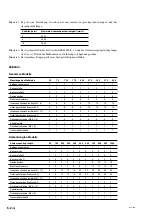
5-2-3. Ausgangskabellänge (nur für Analogausgabe)

Es gibt eine Beziehung zwischen der maximalen Ansprechgeschwindigkeit und der Ausgangskabellänge.

Kabellänge (m)

Maximale Ansprechgeschwindigkeit (mm/s)

3

3000

9

2330

15

1660

Das System erfüllt nicht die Vorschrift EN61000-6-2, wenn die Stromversorgungsleitung länger als 10 m
ist. Treffen Sie Maßnahmen zur Verhütung von Spannungsstößen.

Die maximale Ansprechgeschwindigkeit hängt vom Widerstand des Ausgangskabels, der Kabelkapazität,
der Empfängerlast usw. ab.

Summary of Contents for BL57-003NE Series

Page 1: ...instructions in the manual carefully before use and strictly follow them Keep the manual for future references Lesen Sie die ganze Anleitung vor dem Betrieb aufmerksam durch und folgen Sie beim Betri...

Page 2: ...BL57 NE...

Page 3: ...operating installing maintaining in specting repairing or otherwise working on this unit Warning indication meanings The following indications are used throughout this manual and their contents shoul...

Page 4: ...aser is 6 mW class 3B Although the laser beams emitted from the head interior are invisible to the eye they are hazardous to the human body Therefore never disassemble the scale unit or try to look in...

Page 5: ...3 DU CANADA 3 188 177 22 q w e CERT I F I CAT I ON P O P OWER R S U S UPPLY DC 5 V 5 V Magnescale Co Magnescale Co Ltd MAD ADE E IN N JAP APAN PRODUC T C T C O C OMPL I E S E S W I W I T H T H D HHS S...

Page 6: ...ding force cable bear etc In such a case bend the cable connected to the output connector on the interface unit Notes on attachment location Attach the scale in a location as near as possible to the w...

Page 7: ...ATION IS SUBJECT TO THE FOLLOWING TWO CONDITIONS 1 THIS DEVICE MAY NOT CAUSE HARMFUL INTERFERENCE AND 2 T H I S D E V I C E M U S T A C C E P T A N Y INTERFERENCE RECEIVED INCLUDING I N T E R F E R E...

Page 8: ...6 E BL57 NE...

Page 9: ...For output format F and G only 4 3 4 4 1 Detailed Description of MODE Switches 4 4 4 5 Changing the Settings For output format F and G only 4 4 4 5 1 Changing the Direction 4 4 4 5 2 Changing the Res...

Page 10: ...ii E BL57 NE...

Page 11: ...0 1 0 1 0 05 0 02 0 01 m Analog output type 0 4 m Head signal cycle of 0 4 m allows the interpolation error to be disregarded Optical integrated circuits employing the latest semiconductor technology...

Page 12: ...01 m BL57 056NEFB Soda lime glass 560 mm Open type with no reference point A B signal output 0 1 0 05 m BL57 066NEHB Soda lime glass 660 mm Open type with no reference point Analog output 0 4 m Model...

Page 13: ...BL57 NE E 2 1 2 Names and Functions of Parts Fig 2 1 Reference plate Head cable Detector head Scale Interface unit Mounting screw Plain washer Spacer Scale clamp Cable clamp Pan head screw...

Page 14: ...2 2 E BL57 NE...

Page 15: ...have matching serial numbers Consider the mounting position Abbe error and the environmental conditions temperature humidity vibration and dust thoroughly Do not lead the head cable through the same...

Page 16: ...sure to an accuracy of 2 1000 mm Dial gauge stand 1 Oscilloscope 1 Capable of 2 quadrant X Y display Input sensitivity DC 0 1 V DIV X Y frequency band 1 MHz or more Tools Hex wrenches 3 mm 1 5 mm 1 ea...

Page 17: ...2 50 1 969 75 2 953 100 3 937 120 4 724 120 4 724 75 2 953 100 3 937 L3 75 2 953 100 3 937 P 4 6 8 8 8 10 10 12 12 25 0 2 0 984 0 008 L1 For BL57 003NE C 012NE C 017NE C 022NE C 037NE C 042NE C Detect...

Page 18: ...6NE B BL57 066NE B BL57 076NE B BL57 086NE B BL57 096NE B BL57 106NE B Measuring length 560 22 047 660 25 984 760 29 921 860 33 858 960 37 795 1060 41 732 L1 596 23 465 or more 696 27 402 or more 796...

Page 19: ...essed against the reference plate for parallelism when mounting The reference plate is vital to accurate scale mounting Be sure to always use the supplied screw and mount it exactly as described in th...

Page 20: ...57 003NE BL57 006NE 007NE 026NE 027NE 032NE 046NE BL57 012NE 016NE 017NE 022NE 036NE 037NE 042NE M4 Plain washer nominal 4 Reference plate Scale clamp M4 Plain washer nominal 4 Reference plate Scale c...

Page 21: ...um surface of the scale see Fig 3 5 lightly against the reference abutment surface Note Gradually and alternately tighten screws A and B of the scale clamp indicated in the figure Use only the left si...

Page 22: ...ale is installed with deformation the specified accuracy cannot be achieved This also applies to the following procedures If it appears that the scale has been bent by force loosen the scale clamp and...

Page 23: ...and dust on the surface thoroughly 3 4 Detector Head Mounting 1 Move the machine table and adjust the mounting position of the detector head to roughly the center of the scale 2 Use the supplied mount...

Page 24: ...X Y mode 4 Set the deviation sensitivity VOLTS DIV of CH1 and CH2 to 0 5 V DIV 5 Set the input coupling switches of CH1 and CH2 of the oscilloscope to GND and adjust the position of the oscilloscope s...

Page 25: ...ut type Output format H Amplitude 0 6 Vp p to 1 1 Vp p Fig 3 14 1 Loosen the detector head mounting screws and then bring the stopper directly against the scale bottom surface 2 Rotate the detector he...

Page 26: ...p Analog output type Output format H Amplitude 0 6 Vp p to 1 1 Vp p For output format A the center of the Lissajous figure is 0 V For output format F G and H the center of the Lissajous figure is 2 5...

Page 27: ...ent Secure the cable with the supplied cable clamp and pan head screw M4 8 Before using the scale to perform measurements allow the scale to set for about three hours after mount ing so that the secur...

Page 28: ...BL57 NE 3 14 E...

Page 29: ...screws in their original positions Tightening torque 0 3 N m Be careful not to lose the screws when you remove them When attaching the interface unit cover be sure that the protruding surface is on th...

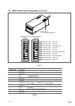
Page 30: ...evel alarm lamp CERT I T I F I CAT I O I ON P O P OWER R S U S UPPLY DC 5 V 5 V Magnescale Co Magnescale Co Ltd Ltd MAD ADE E IN N JAPAN PRODUC T C T C O C OMPL I E S E S W I W I T H T H D HHS S R U L...

Page 31: ...Mode 9 Always OFF 10 Always OFF Table 4 1 MODE switch 1 Always off MODE switch 2 Always off MODE switch 3 Direction switch MODE switch 4 Always off MODE switch 5 Always on MODE switch 6 Resolution se...

Page 32: ...ON sets 0 02 m and setting to OFF sets 0 01 m MODE switch 8 Alarm mode switch This switch is used to select the alarm output format For more information see section 4 5 3 Setting the Alarm Reset Mode...

Page 33: ...e If the cause of the alarm is not cleared within approximately 400 ms it will be reset once the cause of the alarm has been cleared This mode is the default setting Hold mode When the scale is in ala...

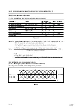
Page 34: ...e minimum phase error can vary depending on the length of the output cable cable capacity receiver load and other factors In output format F and G the A B output signal is synchronized by a 26 3 MHz i...

Page 35: ...voltage VOA VOA 50 0 50 mV VOB VOB Gain unbalance 6 0 6 System 1 Load resistance 120 Table 4 5 Note 1 When terminator Z0 120 refer to section 5 fig 5 6 supply voltage 5V 5 voltage of load resistance...

Page 36: ...4 8 E BL57 NE...

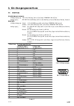
Page 37: ...Shell DE C8 J9 F2 1R manufactured by Japan Aviation Electronics Industry Limited Pin Input output specifications arrangement A B signal output Analog output Output format A F G Output format H 1 A CO...

Page 38: ...uce the supply voltage drops occurring due to the cable length In this case connect the cable to the respective 5 V power supply or 0 V Connect the controller s power supply ground to the power supply...

Page 39: ...mmon mode voltage between the line driver and line receiver is stipulated as 12 V Using the scale when the common mode voltage of 12 V is exceeded can damage the scale To prevent problems between the...

Page 40: ...from sources other than the controller Fig 5 5 When receiving power from sources other than the controller the controller s power supply ground and the power supply ground of the power supply unit hav...

Page 41: ...1 Z0 R1 R1 R2 R2 Z0 R1 R1 R2 R2 When receiving power from sources other than the controller connect the controller s power supply ground to the power supply ground of the power supply unit to place th...

Page 42: ...ble length Cable length m Maximum response speed mm s 3 3000 9 2330 15 1660 The system will not be compliant with EN61000 6 2 if the power supply line exceeds 10 m Devise and implement measures to pre...

Page 43: ...mum phase Max 7 5 MHz difference 80 ns difference 38 ns difference 38 ns Alarms Signal level error Max response speed exceeded or None A B output signal is None Signal level error in high impedance Wh...

Page 44: ...1 1 1 1 1 1 1 1 Accuracy table 1 1 1 1 1 1 1 1 1 Soda lime glass models Scale measuring length 60 160 260 360 460 560 660 760 860 960 1060 Instruction manual 1 1 1 1 1 1 1 1 1 1 1 Reference plate 0 1...

Page 45: ...622 396 15 591 446 17 559 50 1 969 75 2 953 100 3 937 120 4 724 120 4 724 75 2 953 100 3 937 75 2 953 100 3 937 1 2 3 3 3 4 4 5 5 2 2 2 2 2 4 4 2 4 6 6 6 8 8 10 10 Unit mm inch Model Measuring length...

Page 46: ...984 0 008 25 0 2 0 984 0 008 25 0 2 0 984 0 008 88 0 3 3 465 0 012 98 3 858 40 0 2 1 575 0 008 Reference plate W SC Scale clamp SP Spacer P M4 10 Scale clamp mounting screw Detector head mounting scr...

Page 47: ...6NE B BL57 076NE B BL57 086NE B BL57 096NE B BL57 1060NE B 596 23 465 696 27 402 796 31 339 896 35 276 996 39 213 1096 43 150 560 22 047 660 25 984 760 29 921 860 33 858 960 37 795 1060 41 732 100 3 9...

Page 48: ...7 4 E BL57 NE...

Page 49: ...n cable damage deformation of the scale unit or other conditions detrimental to the functioning of the scale If any of these events occur immediately stop the machine and contact your Magnescale Co Lt...

Page 50: ...8 2 E BL57 NE...

Page 51: ...tallation Wartung Inspektion oder Reparatur dieses Ger tes oder der Durchf hrung anderer Arbeiten durch Bedeutung der Warnhinweise Bei der Durchsicht dieses Handbuchs werden Sie auf die folgenden Hinw...

Page 52: ...aximale Ausgangsleistung des Lasers betr gt 6 mW Klasse 3B Obwohl die vom Kopf Innenbereich abgegebenen Laserstrahlen f r das Auge unsichtbar sind stellen sie eine Gefahr f r den menschlichen K rper d...

Page 53: ...CERT I F I CAT I ON P O P OWER R S U S UPPLY DC 5 V 5 V Magnescale Co Magnescale Co Ltd MAD ADE E IN N JAP APAN PRODUC T C T C O C OMPL I E S E S W I W I T H T H D HHS S R U L U L E S S 2 1 2 1 C F R...

Page 54: ...der Montage der Ma stabseinheit besonders sorgf ltig um Rauschen und elektromagnetische St rbeeinflussung von anderen Ger ten zu verh ten F hren Sie das Kopfkabel und dasVerbindungskabel nicht durch d...

Page 55: ...e zu gew hrleisten Vergewissern Sie sich vor und w hrend des Betriebs da das Produkt einwandfrei funktioniert Treffen Sie angemessene Sicherheitsma nahmen um im Falle von Funktionsst rungen Sch den zu...

Page 56: ...ATION IS SUBJECT TO THE FOLLOWING TWO CONDITIONS 1 THIS DEVICE MAY NOT CAUSE HARMFUL INTERFERENCE AND 2 T H I S D E V I C E M U S T A C C E P T A N Y INTERFERENCE RECEIVED INCLUDING I N T E R F E R E...

Page 57: ...chnungen 4 2 4 4 MODE Schalter nur f r Ausgabeformat F und G 4 3 4 4 1 Ausf hrliche Beschreibung der MODE Schalter 4 4 4 5 ndern der Einsellungen nur f r Ausgabeformat F und G 4 4 4 5 1 ndern der Rich...

Page 58: ...ii G BL57 NE...

Page 59: ...g A B Signalen Ausgangstyp 0 1 0 1 0 05 0 02 0 01 m Analogausgangstyp 0 4 m Dank dem Kopfsignaltakt von 0 4 m kann der Interpolationsfehler au er Betracht gelassen werden Nach modernster Halbleitertec...

Page 60: ...Messl nge zwischen 430 und 670 mm besitzt Tabelle 1 1 Abb 1 1 Beispiele BL57 007NEAC Neoceram 70 mm Offener Typ ohne Bezugspunkt A B Signalausgabe 0 1 m BL57 027NEGC Neoceram 270 mm Offener Typ ohne...

Page 61: ...Bezeichnung der Teile und ihre Funktionen Abb 2 1 Bezugsplatte Kopfkable Detektorkopf Ma stab Schnittstelleneinheit Befestigungsschraube Abstandsst ck Ma stabsklammer Unterlegscheiber Kabelklemme Fla...

Page 62: ...2 2 G BL57 NE...

Page 63: ...und Umgebungsbedingungen Temperatur Luftfeuchtigkeit Vibrationen und Staub sind entsprechend zu ber cksichtigen Verlegen Sie das Kabel des Detektorkopfes oder dasVerbindungskabel nicht im gleichen Kab...

Page 64: ...2 1000 mm Messuhrst nder 1 Oszilloskop 1 M glichkeit zur 2 Quadrant X Y Anzeige Eingangsempfindlichkeit DC 0 1 V DIV X Y Frequenzband 1 MHz oder mehr Werkzeuge Sechskant Stiftschl ssel 3 mm 1 5 mm je...

Page 65: ...it mm 13 5 0 2 32 5 0 2 L3 1 25 0 2 L2 1 25 0 2 L1 50 0 3 25 0 2 L2 1 L2 1 L2 1 L3 1 25 0 2 25 0 2 19 5 F r BL57 003NE C 012NE C 017NE C 022NE C 037NE C 042NE C 25 0 2 88 0 3 40 0 2 25 0 2 13 0 2 20 5...

Page 66: ...che muss innerhalb von 0 02 mm ber einen Bereich von 7 mm Breite 200 mm L nge liegen Kalknatronglas Modelle Abb 3 3 Modell BL57 056NE B BL57 066NE B BL57 076NE B BL57 086NE B BL57 096NE B BL57 106NE B...

Page 67: ...ent 1 4 N m Die Bezugsbohrung befindet sich auf der linken Seite wie in der Abbildung gezeigt Nehmen Sie die Einstellung auf der rechten Seite vor w hrend Sie die Parallelit t mit der Hebel Messuhr be...

Page 68: ...BL57 003NE BL57 006NE 007NE 026NE 027NE 032NE 046NE BL57 012NE 016NE 017NE 022NE 036NE 037NE 042NE 2 Befestigen Sie die Ma stabsklammern provisorisch 1 oder 2 ganze Umdrehungen weniger als die halb a...

Page 69: ...iehe Abb 3 5 leicht gegen die Sto grundfl che dr cken Hinweis Ziehen Sie die in der Abbildung mit A und B gekennzeichneten Schrauben der Ma stabsklammer schrittweise und abwechselnd an Verwenden Sie n...

Page 70: ...iert kann die angegebene Genauigkeit nicht erzielt werden Dies gilt auch f r die folgendenVerfahren Falls derVerdacht aufVerzug des Ma stabs durch berm ige Kraftanwendung besteht l sen Sie die Ma stab...

Page 71: ...Oberfl che verschmutzt ist wischen Sie sie mit alkoholgetr nkter Gaze ab Wischen Sie l und Staub gr ndlich von der Oberfl che ab 3 4 Montage des Detektorkopfes 1 Verschieben Sie den Maschinentisch und...

Page 72: ...r TIME DIV auf X Y MODE 4 Stellen Sie die Deviationsempfindlichkeit VOLTS DIV von CH1 und CH2 auf 0 5 V DIV ein 5 Stellen Sie die Eingangskopplungsschalter von CH1 und CH2 des Oszilloskops auf GND und...

Page 73: ...Ausgabeformat H Amplitude 0 6 Vs s bis 1 1 Vs s Abb 3 14 1 L sen Sie die Detektorkopf Befestigungsschrauben und bringen Sie dann den Anschlag direkt mit der Unterseite des Ma stabs in Ber hrung 2 Dre...

Page 74: ...s Typ mit Analogausgabe Ausgabeformat H Amplitude 0 6 Vs s bis 1 1 Vs s F rAusgabeformatA entspricht die Mitte der Lissajousfigur 0V F rAusgabeformat F G und H entspricht die Mitte der Lissajousfigur...

Page 75: ...das Kabel mit der mitgelieferten Kabelklemme und der Flachkopfschraube M4 8 Bevor Sie den Ma stab f r Messungen benutzen lassen Sie ihn nach der Montage etwa drei Stunden lang ruhen damit sich die be...

Page 76: ...BL57 NE 3 14 G...

Page 77: ...nglichen Positionen an Anzugsmoment 0 3 N m Achten Sie beim Entfernen darauf dass die Schrauben nicht verloren gehen Achten Sie beim Anbringen der Schnittstelleneinheitsabdeckung darauf dass die vors...

Page 78: ...format A Stromversorgungslampe Pegelalarmlampe CERT I F I CAT I ON P OWER S UPPLY DC 5 V Magnescale Co Ltd MAD ADE E IN N JAP APAN PRODUC T C T C O C OMPL I E S E S W I W I T H T H D HHS S R U L U L E...

Page 79: ...ung 9 Immer OFF 10 Immer OFF Tabelle 4 1 MODE Schalter 1 immer OFF MODE Schalter 2 immer OFF MODE Schalter 3 Richtungsschalter MODE Schalter 4 immer OFF MODE Schalter 5 immer ON MODE Schalter 6 Aufl s...

Page 80: ...02 m und bei Einstellung auf OFF 0 01 m MODE Schalter 8 Alarmmodusschalter Dieser Schalter dient zur Wahl des Alarmausgabeformats Weitere Informationen dazu in Abschnitt 4 5 5 Einstellen des Alarmzur...

Page 81: ...che jedoch l nger als etwa 400 ms bestehen wird der Alarm nicht eher aufgehoben bis die Alarmursache beseitigt wird Dieser Modus ist die Standardeinstellung Haltemodus Befindet sich der Ma stab im Ala...

Page 82: ...abeformat F und G 38 ns Abb 4 5 Der minimale Phasenfehler kann je nach der L nge des Ausgangskabels der Kabelkapazit t der Empf ngerlast und anderen Faktoren unterschiedlich sein Da das A B Ausgabesig...

Page 83: ...Verst rkungsungleichheit 6 0 6 System 1 Lastwiderstand 120 Tabelle 4 5 Hinweis 1 WennAbschlusswiderstand Z0 120 SieheAbsatz 5 Abb 5 6 Versorgungsspannung 5V 5 Spannung des Lastwiderstands an beiden En...

Page 84: ...4 8 G BL57 NE...

Page 85: ...Industry Limited Geh use DE C8 J9 F2 1R hergestellt von der Firma Japan Aviation Electronics Industry Limited Stiftanordnung Ein Ausgangsspezifikationen A B Signalenausgang Analogausgang Ausgabeforma...

Page 86: ...annungsabfall zu reduzieren Schlie en Sie das Kabel in diesem Fall an das entsprechende 5 V Stromquelle oder 0 V an Schlie en Sie die Stromquellenerde des Steuerger tes an die Stromquellenerde des Ger...

Page 87: ...dem Leitungsempf nger auf der Basis der Norm EIA 422 mit 12 V angegeben Wird der Ma stab verwendet wenn die Gleichtaktspannung von 12V berschritten wird kann der Ma stab besch digt werden Um Probleme...

Page 88: ...em Steuerger t Abb 5 5 Bei Empfang der Stromversorgung von einer anderen Quelle als dem Steuerger t haben die Stromquellenerde des Steuerger tes und die Stromquellenerde des Ger tes das den Strom lief...

Page 89: ...Z0 R1 R1 R2 R2 Bei Empfang der Stromversorgung von einer anderen Quelle als dem Steuerger t schlte en Sie die Stromquellenerde des Steuerger tes an die Stromquellenerde des Ger tes an das den Strom l...

Page 90: ...ge Kabell nge m Maximale Ansprechgeschwindigkeit mm s 3 3000 9 2330 15 1660 Das System erf llt nicht die Vorschrift EN61000 6 2 wenn die Stromversorgungsleitung l nger als 10 m ist Treffen Sie Ma nahm...

Page 91: ...geschwindigkeit 1 000 mm s 1 500 mm s 0 1 m 300 mm s 0 02 m 3 000 mm s Hinweis 1 650 mm s 0 05 m 120 mm s 0 01 m Minimale Minimale Minimale Max 7 5 MHz Phasendifferenz 80 ns Phasendifferenz 38 ns Phas...

Page 92: ...8 8 10 10 12 12 Innensechskantschraube M2 12 2 2 2 2 2 2 2 2 2 Unterlegscheiben Nennma 2 2 2 2 2 2 2 2 2 2 Flachkopfschraube M2 6 5 4 4 4 4 4 4 4 4 4 Kabelklemme 1 1 1 1 1 1 1 1 1 Flachkopfschraube M...

Page 93: ...022NE C 037NE C 042NE C Bezugsplatte 2 M4 8 Bezugsplatten Befestigungsschraube Kabell nge 300 2 M4 8 Bezugsplatten W Befestigungsschraube Detektorkopf Befestigungsschraube 2 M2 12 Montageloch 2 4 Sto...

Page 94: ...be Bezugsplatte W Kabell nge 300 SC Ma stabsklammer SP Abstandsst ck 2 M4 10 Bezugsplatten W Befestigungsschraube P M4 10 Ma stabsklammer Befestigungsschraube Detektorkopf Befestigungsschraube 2 M2 12...

Page 95: ...75 5 13 11 26 BL57 106NE B 1060 1096 75 300 75 6 15 13 30 P M4 10 Ma stabsklammer Befestigungsschraube 2 Bezugsplatte D 2 M4 10 Bezugsplatten Befestigungsschraube SC Ma stabsklammer SP Abstandsst ck...

Page 96: ...7 4 G BL57 NE...

Page 97: ...ie Ma stabseinheit verformt wird oder eine andere Situation eintritt die sch dlich f r die Funktion des Ma stabs ist Halten Sie sofort die Maschine an und kontaktieren Sie dann eine Magnescale Co Ltd...

Page 98: ...8 2 G BL57 NE...
Page 99: ...ent l usage des acqu reurs de l quipement d crit dans ce manuel Magnescale Co Ltd interdit formellement la copie de quelque partie que ce soit de ce manuel ou son emploi pour tout autre but que des op...

Page 100: ...Isehara shi Kanagawa 259 1146 Japan 1 16 16 For foreign customers Note This product or technology may be restricted by the government in your country Please make sure that end use end user and country...

Reviews: