


Laser 5091 Code Reader User’s Guide
Laser 5091 Code Reader User’s Guide
15
14
Accessories Included
No.
Signal Word
Hazard Level
1
User’s Manual
Provides operation instructions for the usage of
code reader.
2
USB Cable
Provides USB communication for updates of
software and DTCs.
3
OBDII Cable
Provides connection for vehicle’s DLC.
4
Cell Battery
Provides power to the code reader when
disconnected from vehicle.
Specifi cations
No.
Item
Specifi cation
1
Display
Backlit, 160 x 105 pixel display with contrast
adjustment.
2
Working
Temperature
0 to 60°C (32 to 140°F)
3
Storage
Temperature
-20 to 70°C (-4 to 158°F)
4
External Power
8-18 Volts powered by vehicle battery
5
Internal Power
9v
6
Dimensions
(L*W*H*) 185mm*85mm*35mm (7.28*3.35*1.38in)
7
Weight
1kg
Display Indicators
Below is a list indictors used to help navigate through menus.
No.
Indicator
Description
1
$
Indicates the control unit number.
2
Indicates more than one screen of information is
available.
3
?
Indicates help information available.
4
G
Indicates graphic viewing of PID is available.
5
Indicates internal battery volume.
Power
The code reader is powered up by vehicle battery when diagnosing; and it is
powered up by internal battery when off-vehicle reviewing test results and printing.
√ Refer to
Code Reader Does Not Power Up
on
page 62
of
Troubleshooting
if there are problems.
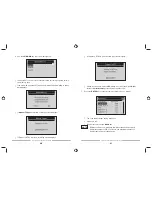
Internal Battery
To power on the code reader by internal battery:
1. Install 9V battery.
2. Press
the
POWER
key to turn on the code reader.
√
When the icon appears, refer to
Battery Replacement
in on page 61 of
Troubleshooting
to replace the battery.
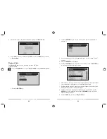
√
When powered from the battery, the code reader disables the display’s
backlighting and turns off automatically after a period of inactivity.
If the code reader will not be used for an extended period of
time, remove the battery to prevent battery leakage from
damaging the battery compartment.
Do not use a Lithium (Li) battery.
IMPORTANT
IMPORTANT