5
4.0 OPERATION
4.1 Before Using the Pump:
1. Check all system fittings and connections to be sure
they are tight and leak free.
2. Check oil level in reservoir before operating pump.
Refer to instructions in Section 5.1.
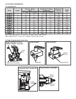
CAUTION
Never add extensions to pump handle.
Extensions cause unstable pump operation.
WARNING
Always keep your body to the side of the
pump, away from the line of force of the handle.
Note:
To reduce handle effort at high pressure, take short
strokes. Maximum leverage is obtained in the last 5° of
stroke.
Note:
When operating a non-vented pump in the vertical
position, the hose end must be pointed down, or the pump
will pick up air and will not build pressure properly.
4.2 Using Two-Speed Pumps
(Models W20307, W20807, W21807, W22607,
X22607, W24507, X24507, W26507 and X26507)
These pumps provide 2-stage flow. Under no-load, the
pump operates in the high flow first stage for rapid advance.
When the load is contacted, the pump automatically
transfers over to the second stage for building pressure.
Note:
Models W22607, X22607, W24507, X24507, W26507
and X26507: when pump pressure reaches approximately
40 bar, you must momentarily stop pumping and raise the
handle to shift to the high pressure stage. After the pump
shifts, pumping will require less effort.
4.3 Single-Acting Applications with Release Valve
(Models W10607, W11407, W20307, W20807,
W21807, W22607 and W24507)
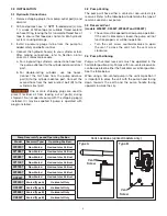
1. Close release valve by turning clockwise, as shown in
Figure 1.
Figure 1
CAUTION
Close release valve -
HAND TIGHT ONLY
.
Using tools on release valve can damage it and cause the
pump to malfunction.
2. Operate pump handle to deliver hydraulic power to
system. Pressure will be maintained until release valve
is opened.
3. Open release valve (turn counter-clockwise) to release
pressure, allowing oil to flow back to the reservoir.
Slowly open release valve to release the pressure and
control the flow of oil back to the reservoir.
Note:
The amount that the release valve is opened controls
the speed of the oil returning to the pump and the retract
speed of the cylinders lowering the load.
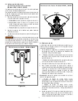
4.4 Single-Acting Applications with 3-Way, 2 Position
Manual Valve (Model W26507)
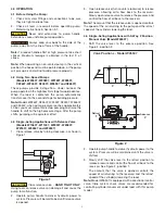
1. Shift the valve lever to the
advance
position. See
Figure 2, position 2.
Figure 2
2
1
2
1
A
A
Retract
Advance
Valve Positions - Model W26507
2. Operate pump handle to deliver hydraulic power to the
system. Pressure will be maintained until the valve is
shifted.
3. Slowly shift the valve lever to the
retract
position to
release pressure and control the flow of oil back to the
reservoir. See Figure 2, position 1.
The amount that the valve is opened controls the
speed of oil returning to the reservoir and the retract
speed of the cylinder(s) lowering the load.
Note:
Model W26507 is equipped with a directional control
valve. Inline system check valves are recommended for
controlling cylinder movement under load with this pump
model.


