


Tologintothe camerafrom acomputeronthe samelAN:
'
iRunas
l
adm
i
nistr
a
t
o
r
O
p
e
n
y
our
M
ic
r
osofl
l
nte
rn
e
t
fa
p
lor
e
r
(I
E)
brow
s
ero
n
y
o
u
r
comp
ut
e
r
an
den
t
e
r
t
he
l
Pad
dr
e
s
so
f
the camera in the URL field. In the example below, the IP address of the camera is 192.168.1100.
2.
In the login window, enter
odmin
for the
User Name
and the password you created in !he
Password
field,
the
click
Login
3. If this is the first time you are logging into a camera, you may see the message in the fo
ll
o
w
i
n
g
scr
ee
n
.
l
f
t
hi
s a
p
p
ea
r
s
,
fo
ll
o
w
th
e
s
ub
-
s
t
e
p
s
be
l
o
w
Clickon the message toinstall theplugin.
b
.
l
nt
he
mes
s
a
g
e
b
a
ra
t
t
h
e
b
o
tt
o
m
o
f
th
e
s
cree
ri
,cl
i
ck
Run
.
Fo
llow
t
h
e o
n
-
scr
ee
n
instructions to install
WebComponents
.
When !he following screen opens, click Finish
The live View screen with the cilmera video image should appear.
Screen select tabs
Capture, Record, Zoom icons
Step 7. Adjust camera pan, tilt and rotaQon
Adjust the camera pan, till and rota1ion to poi flt the camera at your surveillance target. When pointing
the camera, use the
Live View
display on a recorder or remote login. You can also attach the BNC video
maintenancecabletothe connectoron themaintenancepanel,andthenattachit toCVBS monitorto
seealive view videofromthe camera.
While observing
l
i
v
e
v
id
eo from the
came
r
a
,
use the L -wrench to loosen the adjustment
b
r
ac
k
e
t
l
o
ck
sc
re
w
o
n t
h
eb
a
c
k
o
f
t
h
e
ad
j
us
t
m
en
t
bra
ck
e
t
u
m
il
t
he
ca
m
e
r
a
i
s
fr
e
eto
m
o
v
e
a
n
d
r
o
tat
e
.
T
h
e
l
oc
at
ionof
t
h
e
l
oc
ks
cre
w
issho
wnin
thep
h
o
t
oson
pa
g
e
l
o
f
t
h
i
s g
ui
d
e
.
2. Poim
t
he came
r
a a
t
your
su
rv
e
illan
c
e
t
arget
,
chan
gin
g t
he
pan
,
til
t
and rotati
onas
n
e
eded
.
Be
certai
n
t
os
t
a
y
wi
t
hi
n
t
h
e s
p
eci
fi
e
d
p
a
n
,
t
i
l
ta
n
d
ro
t
a
ti
o
n r
a
n
ge
s o
f
th
e
c
a
m
era.See
b
el
ow
Tighten theadjustmentbracketlockscrew1o securelyholdthecamerain p!ace.
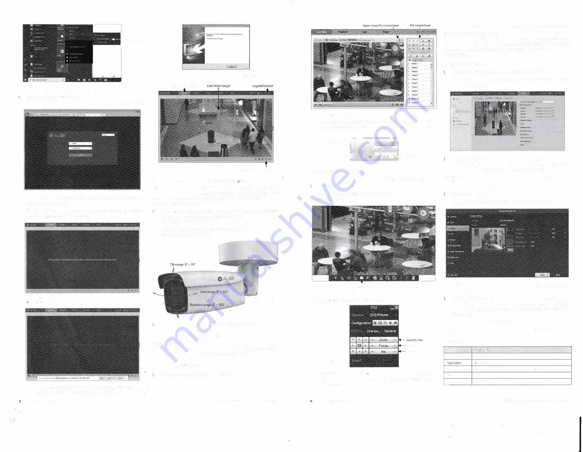
Step 8. Veri�y PTZ functionality
UsethePTZcon
t
ro
l
p
anel
toexe
r
cise t
he
zoomandfocusfu
n
c
t
ionali
t
y o
f
theca
m
e
r
a
.
A
cc
essing
t
o
t
he
control paneldependsonwhe1her1hecamerais installedas adeviceonalA.No1ifilis conne<:tedtoa
NVR. Select the installation type below for your camera to complete this step.
For cameras installed on a LAN
log
into the camera and then open the
Live View
window.
2.
Cli
c
k
t
h
e
j
o
y
st
i
c
ki
con
1
o o
p
e
nthe
P
T
Z
co
n
tr
o
! p
a
n
e
l.
Se
e abov
e
.
3.
In the
PTZ
control
panel,
click each
zoom
and
focus
bLJtton
shown
in
the graphic below.
Verify
t
ha
t
t
h
e c
a
m
e
r
a pe
r
fo
rm
s
a
s
ex
p
ec
t
ed.
R
ef
e
r
t
o
t
h
e
5
pecific
ar
/o
n
ssec
t
i
ono
f
t
h
i
s
d
oc
u
me
n
tfo
r
zoom range.
I' -;-
I . . '
Directionb1.1ttons
--r�
-1--�-l"
ff
.f..
'
.fM.
r
Zoomln/01.ll
�
i
;;
o
i
►
��
�focusln/QUI
Contin1.1ous
......,.-(;"
_.,
T
J
4.
t
·
0
l
O ...._
lrii;
Open
I Close
pao
For cameras connected directly to an NVR
Refer to the firmware manual for your NVR for specific instructions to pirform the fo
ll
o
wi
n
g
Log intotheNVRattheNVR console
2.
In the
Live View
display, find the PTZ camera you installed. Click on the camera to open the
QuickSettingtoolbar.
PTZControlkon
3. C
l
ic
k
the
PTZControl
i
co
n
.
Se
e
a
bove.
4.
·
l
n
t
h
e
p
o
p
-
u
p
P
T
Z
m
en
u
,
c
li
c
k
t
h
e
P
TZContro
l
t
a
b
.S
eeb
e
l
o
w
Focusln/01.ll
hi�Open/Clo-.e
S.
l
nt
h
e
Pl
ZCon
t
ro
l
pane
l,cl
ic
kt
h
ezo
omand
f
oc
us
bu
tt
onslabeledin1hegraphica
b
ov
e.
Ve
r
i
f
y
thatthecameraperformsasexpected.Referto the5pecificoriomsec1ionofthisdocument fm
motion and zoom ranges.
Step 9. Adjust the camera image for your surveillance target
Use
t
h
e
fir
m
w
are
m
en
u
sto
ad
j
u
s
t
1
he
br
ig
h
t
n
e
ss
,
co
ntr
a
s
t,
s
a
t
u
ra
ti
o
n
a
n
d
s
h
a
r
p
n
e
ss
of
t
h
e
v
i
d
e
o
i
m
age
i
f
n
ec
e
ssar
y
.
T
h
ese
s
e
1
1
ing
s
a
r
e
initi
a
ll
y
o
pt
i
m
i
zed
a
tth
e
fac
t
o
r
y
a
n
d m
a
y n
o
t n
ti'
d
a
djus
t
me
nt.
W
h
e
n
adjustments arenecl"isary,thepathstothe imagesettingsmenusare differentifthecamerais installed
as a device on a LAN , or if it
i
s
connected to a NVR. Select the installation type below for your camera to
complete this step
For cameras installed on a LAN
If necessary, log into the camera on the LAN with a
d
min
i
st
r
ative credentials.
2.
Af
ter adjusting
t
hecam
e
ra for thea typ
ic
alfield o
f
view,cl
i
ckthe
Setup
t
ab,andthenclick
t
he
lmagelinkintheleftframe.
·
•·
-
•
-
1
�-...
·
·
-
Adjust1heBrightnessContrast,SaturalionandSharpnessofthe image.Eachparametercanbe
set1oa levelofO-
l
OO ei
t
he
r
bymovi
n
g thesl
i
derorenteringt
h
eva
l
u
e
intheboxon
t
he1igh
t
The effect of the adjustmem will appear in the Live View image in the menu.
Refer to the firmware user manual for your camera to use the other submenus on this screen.
For cameras connected directly to an NVR
logintotheNVR witb administrativeprivileges.
2. Open the firmware Image menu. Go to
Menu I Camera Management I Image
J_
�
In
the
Camera
field drop down list, select the camera
you
want to config
u
re
.
In the example
5.
above,
{Dl)IPCamera 01
is selened
Drag
the
Brightness, Contrast Saturation
and
Hue
adjustment
markers left
or
1ight to
perfect tl1e image
from
1he
camera.
For some adjustmems, you
can
click
the
up (
...
)or
down
( ..-
)
ico
n
s
n
e
a
r t
h
e a
d
j
u
s
t
me
nt
v
al
ue
(
o
n
t
h
e
r
i
g
h
t
s
id
e)
t
o
i
n
cr
e
m
e
n
ta
ll
y
cha
n
g
e
t
h
e
va
l
u
e o
f
those adjustment.
C
li
c
k
Apply
t
o sa
v
e
youiset
t
ing
s
for thi
s
cameia
Refer to the firmware user manual for your NVR to use the other submenus on this screen.
Specifications
Camera
All-NS4116R
lmageSensor
1f2.9'Progres!JveStdn(MOS
PAL/ll!SC
Min.lllumina1100
Color:0.01lux@(F1.2,AGf..ONL0.018Lux@(fl.6,A{.I_QN),OluxwithlR
Slmnerlime
1/3SN:ondto1/100,0005eeond
Slow�hutter
Supported
Summary of Contents for IDCMR-SL-IP-POE-4MP
Page 7: ...2 1 A 1 A 2 L__ __ _ lLlb A 3 A 4 fa fa _ _fa J 8 1 8 2 B 3...
Page 8: ...2 2 2 3 2 4...
Page 9: ...2 5 _ G id m 2 6 2 7 2 8...
Page 10: ...2 9 2 10 3 l L TlO Q B 3 3...