background image

sirio

Ediz. 006 - 12/2017

www.larius.eu

28

Necessary tools and equipment

Necessary tools and equipment

procedure

8.1

 Remove the two valve screws (

8a

8b

)

procedure

9.1

   proceed with disassembly and replace  the 6 seal 

sleeves (

9a

) with pliers


8

9

Necessary tools and equipment

procedure

7.1

  Use a screwdriver to lever the 

lower part of the stud screw 
(

7a

), keeping a hand over the 

cap to accompany it. (

7b

)

7

7a

7b

8b

8a

9a

9a

9a

Summary of Contents for Sirio 27:1

Page 1: ...ITALIANO Ediz 006 12 2017 www larius eu INSTRUCTION MANUAL Sirio 27 1 32 1 ...

Page 2: ...ls mentioned in this manual without prior notice This manual is to be considered as an English language translation of the original manual in Italian The manufacturer shall bear no responsibility for any damages or inconveniences that may arise due to the incorrect translation of the instructions contained within the original manual in Italian ...

Page 3: ...p 14 CLEANING AT THE END OF THE WORK p 14 ROUTINE MAINTENANCE p 15 disassembly and reassembly of the pumping unit p 16 RIPRISTINO MANUALE DEL MOTORE PNEUMATICO p 24 disassembly and reassembly of the pneumatic motor p 25 PROBLEMS AND SOLUTION p 33 Q R S N O P A B C D E F G H J K L M I T U V AIRLESS PNEUMATIC PUMPS FOR SPRAY PAINTING WE ADVISE THE USE OF THIS EQUIPMENT ONLY BY PROFESSIONAL OPERATORS...

Page 4: ...sirio Ediz 006 12 2017 www larius eu 4 White page intentionally ...

Page 5: ... electrical system is equipped with a grounding connection and that it complies with the safety regulations High pressure fluid from gun hose leaks or ruptured components will pierce skin To help prevent injection always Engage trigger lock when not spraying Do not put your hand over the spray tip Do not stop or deflect leaks with your hand body or other Do not point gun at anyone or at any part o...

Page 6: ...beaspiratedandpushedtowards the outlet The unit comes complete with a transportation trolley a high pressure material filter an air supply regulator for the pump a material suction tube complete with filter and a recirculation tube The ratio 27 1 30 1 32 1 45 1 means that the outlet pressure of material is 27 30 32 45 times higher than the pump feed air pressure TECHNICAL DATA 27 1 3 7 bar 189 bar...

Page 7: ...onson recycling process ATEX plate Code Sirio 27 1 Stainless steel Trolley version accessories 99000 Sirio 27 1 Stainless steel complete with FRL unit line filter drain valve suction recirculation system 35014 High pressure hose ø 7 5 m M16x1 5 fitting 11200 AT250 airless spray gun with M16x1 5 revolving fitting 18270 Super Fast Base Clean SFC Airless nozzle choice of size 17200 Toolbox Sirio 32 1...

Page 8: ...ump Filtro alta pressione uscita materiale High pressure filter out material Recirculating cock Recirculation pipe fitting fixing Description POS Description 11 12 13 14 15 16 17 18 19 20 Fluid recirculation pipe Material suction pipe Material suction filter Fitting pipe fitting intake Material pumping group Material flexible pipe Spray technology Cable grounding with gripper Gun AT250 optional Gu...

Page 9: ...sirio Ediz 006 12 2017 www larius eu 9 18 3 1 9 7 8 10 6 2 air 5 16 13 12 11 ...

Page 10: ...refully all the safety rules The personnel must be equipped with the necessary safety clothing The manufacturer will not be responsible for the unlo ading operations and transport to the workplace of the machine Check the packing is undamaged on receipt of the equipment Unpack the machine and verify if there has been any damage due to transportation In case of damage call immediately LARIUS and th...

Page 11: ...nd caused by the injection of a fluid Always DISCONNECT THE SUPPLY AND release the pressure in the circuit before performing any check or part replacement of the equip ment NEVER MODIFY ANY PART IN THE EQUIPMENT CHECK REGULARLY THE COMPONENTS OF THE SYSTEM REPLACE THE PARTS DAMAGED OR WORN Tighten and check all the fittings for connection between pump flexible hose and spray gun before using the e...

Page 12: ...ameter no lower than 10 mm CONNECTION OF SUCTION AND RECIRCULATING PIPES Connect the suction and recirculating pipes to the pump The suction hose can be locked finger tight F1 Use a spanner to tighten the recirculating pipe F2 In both cases do not use sealant agents for fitting threads IF THE PRODUCT TO BE USED IS TOXIC AVOID INHALATION AND CONTACT BY USING PROTECTION GLOVES GOGGLES AND PROPER FAC...

Page 13: ...eequipmenthasbeentestedatourplantwithlightmineral oil left inside of the pumping element as protection Therefore beforesuckingtheproduct carryoutawashingusingadiluent Dip the suction hose F4 into the tank of the washing Insert the recirculating pipe F5 into a container a metal container is suggested Open the recirculating cock F6 F5 F4 Set the pump feed pressure at about 3 bar and open the air pas...

Page 14: ...hose Inthiscase pleasefollowthewashingproceduredescribed on page 8 before using the tooling Store possible dangerous fluids in proper containers Theirdisposalmustbeperformed in accordance with the regulations in force about the industrial waste goods G WORKING Use the machine after carrying out all the setting up ope rations described in the previous paragraph Check all the fittings for connection...

Page 15: ...ely to avoid the seizure of the pumping piston and the wear of seals In case of persistent coming out of product replace the seals MATERIAL SUCTION FILTER Remove and clean the material suction filter I3 High pressure FILTER CLEANING Remove and clean the high pressure filter for material outlet I4 Check periodically the air supply to the pump Ensure the air is always clean and lubricated Atthestart...

Page 16: ...E PUMPING UNIT 2a Necessary tools and equipment Procedure 1 1 Remove the high pressure filter unit from the pump Procedure 3 1 Unscrew and remove the bottom valve body 3a 1 Necessary tools and equipment Procedure 2 1 Remove nuts 2a 2 2a Necessary tools and equipment 3 3a 3a ...

Page 17: ...dure 4 1 Remove the gasket 4a 4 2 Remove the components 4b 4c 4d 4 3 Clean and lubricate the gasket housing and replace it with a spare part 4 4 Reassemble the components 4a 4b 4c 4d Procedure 5 1 Loosen the ring nut 5a without removing it Procedure 6 1 Unscrew and remove the component 6a 4 5 6 4b 4c 5a 4d 6a 6a CLEANER 4a 4a 4b 4d 4c ...

Page 18: ...8b 8 Necessary tools and equipment Procedure 9 1Removethegaskets 9a 9b cleanandlubricatethegaskethousing and replace them with new spare parts 9 Procedure 7 1 Remove the gasket 7a 7 2 Clean and lubricate the gasket housing 7 3 Replace the gasket with a spare part 7 8b 9a 9b Necessary tools and equipment 7a CLEANER 8a 8b CLEANER 9a 9b ...

Page 19: ...component 10a Procedure 11 1 Remove the complete gasket pack 11a 11 Procedure 12 1 Remove the component 12a 12 2 Clean and lubricate the gasket housing and replace it with the new one 12b 12 3Reassemblethecomponent 12a 12 12a 10a 10a Necessary tools and equipment 11a CLEANER 12b 12a ...

Page 20: ...h the new spare parts 13a A Female steel ring B PTFE V seal ring C Polypropylene V seal ring D Male steel ring E Gasket housing Follow the direction of rotation of gaskets NOTE Direction of assembly 13 Necessary tools and equipment 14 Procedure 14 1 Reassemble the component 14a 14a 14a CLEANER 13a A B C B C B D E ...

Page 21: ...d replace them with new spare parts A Male steel ring B PTFE V gasket C POLYETHYLENE V gasket D Female steel ring E Ball F Piston valve A Anello maschio in acciaio B guarnizione in PTFE V C guarnizione in POLYETHYLENE V D Anello femmina in acciaio E Sfera F Valvola pistone Direction of assembly Direction of assembly Followthedirectionof rotation of gaskets Followthedirectionof rotation of gaskets ...

Page 22: ...reassemble the component 17a 17 Necessary tools and equipment Procedure 18 1 Reassemble the component 18a as shown in the figure 18b 18 Necessary tools and equipment Procedure 19 1 Insert the component 19a inside the component 19b 19 1 Using a wrench screw in the component 19a 19 19b 17a CLEANER 18a 18b 19a 19a CLEANER ...

Page 23: ...y tools and equipment Procedure 20 1 Tighten the ring nut 20a 20 Procedure 21 1 Reassemble the bottom valve body 21a Necessary tools and equipment 21 Necessary tools and equipment Procedure 22 1 Reassemble the nuts 22a 22 20a 21a 21a CLEANER 22a 22a ...

Page 24: ... again a blocked motor close the air supply and release pressure in the plant This operation should allow the recovery of the valves In case the motor is blocked proceed as follows Close the air supply to the pump and release the residual pressure in the plant unscrew the motor cap K1 and pull it upward along with the guide rod K2 so as to manually trigger the stroke inversion unit screw again the...

Page 25: ...e residual pressure in the plant 1 2 Unscrew the motor cap 1a and pull it upwards together with the guide rod 1b 1e 1 3 Hold the guide rod 1b and remove the plug 1a using two wrenches 1 Necessary tools and equipment Replace immediately the plug with a usual M8 1C nut before the guide rod 1B slides into the cylinder 1D 1e 1a 1a 1b 1c 1a 1b 1b 1c 1c 1d 1c ...

Page 26: ...io Ediz 006 12 2017 www larius eu 26 2 Necessary tools and equipment Procedure 2 1 Remove the screws 2a and the washers 2b 2c 2d Procedure 3 1Carefullyextractthemotorcylinder 3a fomthepump 3 3a 2c 2d 2b 2a ...

Page 27: ...t 4a holding the guide rod with a 7mm wrench Then reassemble the cap 4b 4 Procedure 5 1 Press at the point 5a to snap inside the rocker arm stud screw Procedure 6 1 Unscrew and remove the two screws 6a 6b with 2 13mm wrenches as shown in figure 6c 5 6 Necessary tools and equipment 4a 4b 5a 6a 6b 6c ...

Page 28: ...cedure 8 1 Remove the two valve screws 8a 8b Procedure 9 1 Proceed with disassembly and replace the 6 seal sleeves 9a with pliers 8 9 Necessary tools and equipment Procedure 7 1 Useascrewdrivertoleverthe lower part of the stud screw 7a keeping a hand over the cap to accompany it 7b 7 7a 7b 8b 8a 9a 9a 9a ...

Page 29: ...0a 10b 10 Procedure 12 1 Reassemble the two valve screws 12a as shown in the drawing 11 12 Necessary tools and equipment Necessary tools and equipment Procedure 11 1 Remove the OR gasket 11a and replace it if necessary with a spare part CLEANER 12a Follow the direction of rotation of gaskets NOTE 10a 10b 11a ...

Page 30: ...ngandadjusting the exact position of the stud screw as shown in the drawing keepingatolerance distance of 3 5 mm Make adjustments in the same way on both valve screws NOTE Necessary tools and equipment Procedure 13 1Unscrewthecap 13a holdingtheguiderodwitha7mmwrench Then reassemble the nut 13b 13 3 5 mm of the stud screw valve screw 13b 13a ...

Page 31: ...ry tools and equipment Procedure 15 1 Re screw in the 6 screws 15a and the washers 15b 15c 15d Procedure 14 1 Lubricate the gasket 14a 14 2 Carefully reassemble the motor cylinder 14b on the pump 14 Necessary tools and equipment 14a 14a 15b 15a 15c 15d ...

Page 32: ... Raise the central guide rod 16b from inside the cylinder 16d 16 2 Remove the nut 16c 16 3 Re screw the cap 16a onto the rod using 2 wrenches and re screw in the cap on the cover 16e 16 Necessary tools and equipment 16a 16b 16c 16a 16b 16c 16c 16d 16c 16e ...

Page 33: ... is too large or worn Thespraygun sfilterandthematerial output filter s sieve are too fine Checkontheairsupplyline Incre ase the diameter of the feed hose Open the recirculation tap to checkwhetherthepumpstartsup Unscrew the high pressure filter and clean replace the filter sieve Clean replacethespraygun sfilter Clean the suction filter Reduce feed air pressure Disassemble the motor and verify Add...

Page 34: ...sirio Ediz 006 12 2017 www larius eu 34 White page intentionally ...

Page 35: ... SPARE PARTS N Complete pneumatic motor pag 36 O O Pneumatic regulator pag 37 S Complete trolley pag 41 T U pag 42 Pumping unit coupling kit pag 43 Pumping 155cc 32 1 pag 38 Pumping 180cc 27 1 pag 39 Pumping unit Filter Assembly pag 40 P Q R ...

Page 36: ...TE PNEUMATIC MOTOR Ref 99100 SCREW VALVE COMPLETA RIF 99068 COMPLETE ROCKER ARM RIF 99066 BUSH RIF 96017 40 39 38 31 29 28 27 37 26 25 24 23 19 18 17 16 15 14 13 4 1 5 7 6 3 2 9 10 NOT INCLUDED IN THE MOTOR ASSEMBLY 11 12 8 34 33 32 30 22 21 20 35 36 ...

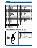
Page 37: ...27 28 29 30 31 32 33 34 35 36 37 38 39 40 41 Q ty 1 6 6 1 1 1 1 1 12 1 1 1 1 1 1 1 1 1 1 1 1 2 2 99100 96050 33005 16111 99270 99054 96211 96210 5010 34020 99052 99064 99065 99069 99055 99056 96019 96017 1 96017 2 96016 33031 99051 99057 99058 Pneumatic regulator unit assembly rif 99291 Pos Guide Spring Screw O ring Seal Bushing Exchange Spring Roller Fork Rocker lever Fork pin Nut Washer Ø 8 Gask...

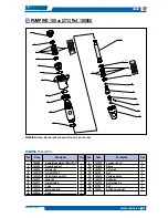
Page 38: ...ts ring nut Female ring Gasket PTFE V Polyethylene gasket V Male ring Gasket holder O ring Pumping group O ring Locking ring nut Sleeve Piston rod Rondella pistone Ball Pumping piston Ball guide Ball locking pin Ball Bottom valve body 1 2 6 4 2 1 1 1 2 1 1 1 1 1 1 1 1 1 1 _ 1 2 3 3A 4 5 6 7 8 9 10 11 12 13 14 15 16 17 18 155050 155011 155012 155007 1 155007 2 155006 155013 155014 155015 155016 155...

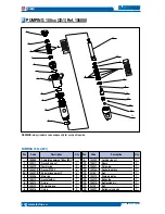
Page 39: ...ethylene gasket V Male ring Gasket holder O ring Pumping group O ring Locking ring nut Sleeve Piston rod Ball Pumping piston Ball guide Ball locking pin Ball Bottom valve body 1 2 6 4 2 1 1 1 2 1 1 1 1 1 1 1 1 1 1 2 3 3A 4 5 6 7 8 9 10 11 12 13 14 15 16 17 180050 180006 180004 180003 1 180003 2 180002 180007 155014 155015 155016 155022 180009 180001 35163 180005 155019 155018 20149 155021 PUMPING ...

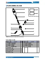
Page 40: ...Tank Filter Sieve Filter Sieve Support O ring Fitting Ball valve Fitting Cap Fitting 1 1 1 1 1 1 2 2 1 1 1 2 3 4 5 6 7 8 9 10 99250 10107 99252 95218 65078 65099 6148 33037 6149 1 95214 3385 Pos Code Description Q ty Seal Washer Filter Base Filter Inlet Fitting 27 1 label 32 1 label 1 1 1 1 1 11 12 13 14 14 33010 99251 99253 99042 99043 FILTER ASSEMBLY Ref 99250 1 2 3 4 6 7 8 9 7 10 8 12 13 11 5 ...

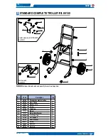
Page 41: ...ndard complete trolley Base Trolley Washer Ø 10 Screw Tube Cap Wheel Wheel Stop Washer Ø 40 Tube Cap Wall Support Heater Holder Screw Split pin Bushing 1 4 4 2 2 2 6 1 1 2 2 2 1 2 3 4 5 6 7 8 9 10 11 12 99150 99153 33005 4408 95159 37238 20305 95229 99156 99154 6130 18902 99155 1 2 7 2 9 10 11 12 3 4 5 6 7 7 8 Heater assembly kit MOD 6099 Ref 99151 Wall support Ref 99157 ...

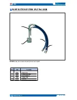
Page 42: ...T SUCTION SYSTEM SPLIT Ref 85026 1 2 3 4 WARNING always indicate code and quantity for each part required Pos Intake system Suction pipe complete Recirculation hose Locking spring Intake filter 85026 18097 16613 18096 37216 1 2 3 4 Code Description ...

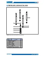
Page 43: ... kit Ref 99280 WARNING always indicate code and quantity for each part required Pos Code Description Q ty Complete kit Tie rod Nut Split pin Or 3050 Joint sleeve Nut Pumping shaft connection 4 4 1 1 1 2 1 1 2 3 4 5 6 7 99280 99281 95013 3323 96073 99282 99284 99283 ...

Page 44: ...NSTOCK FILTERS Code 11039 Green 30M Code 11038 White 60M Code 11037 Yellow 100M Code 11019 Red 200M Code 11131 L91X 1 4 Code 11130 L91X M16x1 5 FILTRO Code 95218 TAMIS 30M Code 95219 TAMIS 60M Code 95220 TAMIS 100M Code 95221 TAMIS 200M FITTING WITH MANOMETER Code 147 M16x1 5 Code 150 1 4 Code 91044 PNEUMATIC MIXER Code 7030 HP FLOW REGULATOR Code 6099 HEATER ...

Page 45: ...FC15 40 SFC15 60 SFC17 20 SFC17 40 SFC17 60 SFC19 20 SFC19 40 SFC19 60 SFC21 20 SFC21 40 SFC21 60 SFC23 20 SFC23 40 SFC23 60 SFC25 20 SFC25 40 SFC25 60 SFC27 20 SFC27 40 SFC27 60 SFC27 80 SFC29 20 SFC29 40 SFC29 60 SFC29 80 SFC31 40 SFC31 60 SFC31 80 SFC33 40 SFC33 60 SFC33 80 SFC39 40 SFC39 60 SFC39 80 SFC43 40 SFC43 60 SFC43 80 SFC51 40 SFC51 60 SFC51 80 GUN EXTENSION Code 153 cm 30 Code 153 cm ...

Page 46: ...PAINT SPRAYING EQUIPMENT Innovation The real kind ...

Page 47: ...1 68 1 ghibli zinc 30 1 sirio 27 1 32 1 sirio plunger piston 30 1 45 1 super NOVA 45 1 68 1 80 1 omega zinc 30 1 ghibli 30 1 40 1 omega 23 1 30 1 34 1 Super omega zinc 34 1 VEGA 23 1 super omega 23 1 34 1 40 1 super nova zinc 45 1 AIRLESS PNEUMATIC PUMPS ...

Page 48: ...LARIUS srl Via Antonio Stoppani 21 23801 Calolziocorte LC ITALY TEL 39 0341 621152 Fax 39 0341 621243 larius larius com Made in Italy 1969 www larius eu ...

Reviews: