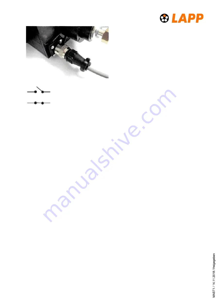
The 2 pole connector mounted on the rear
is connected to a micro-switch inside the
unit: If all connectors are in place and the
unit is locked, the micro switch is locked A
complete assembly instructions for this
connector are shown at the end of this doc-
ument.
Micro switch with POWERLOCK BOX - open
Micro switch with POWERLOCK BOX - closed
4 Installation and usage
4.1 Warnings
This box should only be operated by suitably qualified persons.
Only original POWERLOCK connectors should be used with this unit. The use of non-
approved connectors may cause damage to the box and will invalidate any warranty.
Ensure that the current rating of the cables and connectors being used are suitable for
the current rating of the POWERLOCK BOX and connected supply.
Do not connect / disconnect under load!
4.2 Connection with cable connectors
The necessary mating connectors have to be ordered separately and are not part of the deliv-
ery. Recommended cross-sections are printed on the rear of the box:
400
- 120 mm² and 660 A – 240 mm².
1.
Use the Allen wrench to open the cover (version with safety cover).
2.
The POWERLOCK connectors are plugged sequentially in a row. Starting on the left with
the Ground/Earth connection (Green) going to the right with N, L1, L2, L3.
3.
Insert the Ground (Green) connector, aligning the “PUSH” arrow on the label of the con-
nector in a 12 o´clock position. Fully insert the connector until it bottoms in the cavity
and turn through 45 degrees clockwise until the connector locks with an audible „click‟.
4.
Repeat the above process for the Neutral connector and the rest of the connectors. If at
any time a connectors does not rotate fully, check if the previous connector is fully
turned.
5.
The lock is located to the right of the L3 connector on the front panel. The needed square
drive key is provided.


