


Lantronix
SISTP1040-551-LRT Install Guide
33841 Rev. A
16
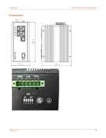
Power Connection
The switch can be powered from
one or two power supplies. Switch power input ranges are:
•
48V-57V for PoE
•
50V-57V for PoE+
•
52V-57V for PoE++
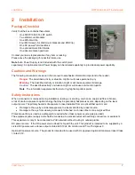
1. Insert the terminal block into the switch top panel receptacle.
2. Insert the positive and negative wires (AWG 14-26) into the PWR + and PWR - contacts on the terminal block
and tighten the wire-clamp screws to prevent the wires from being loosened.
3.
Caution
: DC power must be connected to an isolated power supply. See chapter
below
.
4. Verify proper LED status; see chapter
on page
below.