


A: Compliance and Warranty Information
Micro125 Embedded Device Server Integration Guide
17
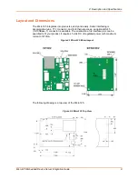
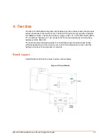
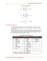
Figure 4-2 Pin Configurations
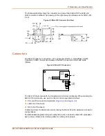
Test Bed Connectors
The Micro125 test bed has four connectors: CON1 (Serial Port 1 or Channel 1), CON2
(TTL Interface), CON4 (Serial Port 2 or Channel 2), and CON3, which is a 5VDC power
supply connector.
This RS-232 level serial interface is implemented with a DB9F connector. The Micro125
converts the RS-232 serial transmit and receive data of this interface to Ethernet protocol
transmit and receive data. The DB9 connector was selected for compatibility with most
PC serial interface ports using a straight through cable.
Table 4-1 Micro125 Test Bed Connectors
CON1 Serial Port
(Channel) 1a
CON2 TTL Interface
CON4 Serial Port
(Channel) 2b
Pin
Signal
Pin
Signal
Pin
Signal
1
DTRA (output)
1
+5 VDC
1
TxB (output)
2
TxA (output)
2
GND
2
RxB (input)
3
RxA (input)
3
TxA (output)
3
GND
4
DCDA (input)
4
RxA (input)
5
GND
5
CTSA (input)
6
None
6
DCDA (input)
7
CTSA (input)
7
RTSA (output)
8
RTSA (output)
8
DTRA (output)
9
None
9
None
10
None
11
TxB (output)
12
RxB (input)
a. CON1 Serial Port (Channel) 1 is also designated as A.
b. CON4 Serial Port (Channel) 2 is also designated as B.