Appendix
BOLERO40 Series Hardware Manual
35
9
Appendix
9.1
Installation guidance
In order to satisfy the upcoming changes of the RED – Radio Equipment Regulation, we
strongly recommend to observe the following recommendations when installing BOLERO40
Series:
1.
When installing BOLERO45, please make sure the device's top side with the text "THIS
SIDE TO THE SKY" is facing up and in full view of the sky and that no metal objects is
interfering GNSS/GSM signals. Try to power the device so it is permanently powered by
car battery instead of its backup battery.
2.
Connect the
BROWN wire (GROUND)
to the negative ground.
3.
Connect the
RED wire (POWER)
to a constant DC power voltage (about the power
supply range, refer to chapter
). Do not connect POWER wire directly to your car
battery but connect it to the fuse box in the car with permanent power. A great location
for installation that provides best access to the GNSS satellites is below the dashboard.
We recommend that you use a steady plus port or an ignition port. (When connected
via the ignition port, the device switches off when the car ignition is turned off.) Please
use a slow 2A fuse. No further current consumer should be connected on the same port
/ use the same fuse.
4.
Connect the
BLUE wire (ignition wire)
to a fuse that only has power (max. 32.0V DC)
when the ignition is on and 0V when it is off. This allows tracking of engine on and off
in the daily activity report and idle time reporting.
5.
Depending on the user application, the
digital outputs
may be connected (max. 32.0
VDC) to activate something e.g. a relay, buzzer, turn on a lamp, etc. The
digital inputs
can be connected (max. 32.0 VDC) to detect opening/closing vehicle’s doors. Voltage
changes on a digital input may be programmed to activate an output, for example, a
relay or buzzer.
Kindly note
, that it is imperative that only qualified, suitably trained staff perform the
installation. These precautions will help prevent risks which might occur e.g. in case of
damage of the installation cable.
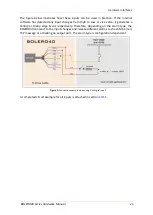
The figure below illustrates a common schematic of how to install BOLERO40 in the vehicle.
For detailed information, refer to the related documents
[
AppNotes_AVL_Installation_Guide.pdf
].
Figure 13:
Schematic example of installation guidance.

