


BOLERO40 Series Application Interface
BOLERO40 Series Hardware Manual
20
5
BOLERO40 Series Application Interface
5.1
Power supply
The power supply for the BOLERO40 series devices has to be a single voltage source of:
V
DC IN
= +10.8 V...+48.0 VDC
The operating voltage (V
DC IN
) has to be applied permanently to the BOLERO40 series
devices and able to provide sufficient current of up to
2 A
(pulse).
NOTE
: Operating voltage range must never be exceeded; care must be taken in order to
fulfill min/max voltage requirements. The short-term voltage peaks of +75 VDC must not
be exceeded at any time. The operating voltage (V
DC IN
and GND) is protected against short-
term voltage spikes and reverse polarity, but
NOT
protected against continuous
overvoltage.
5.1.1
Power lines on the 8-wire harness
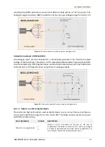
One DC IN pin on the main 8-pin port is dedicated to connect a co12, +24 volt DC
voltage source, and the BROWN wire (GND) to the ground. For more details about the
operating voltage refer to the chapter
Both DC IN and GND wires serve for charging the connected backup battery and also for
powering device.
Signal
name
I/O Parameter
Description
DC IN
I
+10.8 V...+48.0 VDC permanent power
Positive operating voltage. For more
details, see chapter 9.1.1, “Installation
GND
-
0 V
Ground (should be isolated from the
vehicle grounds when the device is going to
be installed in a vehicle).
5.1.2
Automatic shutdown
Automatic shutdown takes effect if:
•
under voltage is detected (internal battery level runs below the nominal voltage and
the external power supply is disconnected)