


Hardware Interfaces
BOLERO40 Series Hardware Manual
27
6.1.1.3
How to use IOs as digital outputs
BOLERO40 supports two IOs which can be used either as input or output. These outputs
are open collectors and can be used to indicator lamps or relays with up to
100 mA @ max
+ 32.0 V DC
. They do not include internally any flyback diodes for protection when
interfacing inductive loads such as relays. Thus, when controlling a relay, it is strongly
recommended to use a fly-back diode as shown in Figure below. To activate these outputs
use the command
$PFAL,IO
5[6]
.Set=high
[low,hpulse,lpulse,cyclic]
for
IO2, IO3
respectively or you can configure one or more alarms that activate these outputs when
specific events occur
(e.g.
$
PFAL,Cnf.Set,AL0=IO.e8=redge:IO5.Set=cyclic,1000,2000
).
In order to evaluate this alarm, send firstly this alarm configuration to the BOLERO40 series
devices and then trigger IGN-pin
(see Figure 6 below)
to High – as result the IO2 goes High
for 1 sec and Low for 2 sec. To set IO2 to Low, just execute the command
$
PFAL,IO5.Set=Low
.
For more details how to activate an output and how to configure
an alarm, refer to the related documents
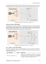
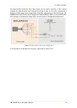
Both figures below show the schematic
connections of how to use this output.
Please note that, the power should not be applied
directly to the IOs configured as outputs without having e.g. a resistor between them.
Figure 5:
Connection example 1 when controlling a relay.
Figure 5.1:
Connection example 2 when controlling an LED.