Lantech
CM-021-GB-II
10/100/1000Base-T to 1000Base-FX Switch Converter
User Guide
Rev.1.01
Aug 2008
Page 1: ...Lantech CM 021 GB II 10 100 1000Base T to 1000Base FX Switch Converter User Guide Rev 1 01 Aug 2008...
Page 2: ......
Page 3: ...story 10 100 1000Base T to 1000Base FX Switch Converter Document Release Date Revision Initials 1 00 Aug 18 2008 First release E C 1 01 Sep 11 2008 Add dimension picture and modify the power consumpti...
Page 4: ...Content Introduce 1 FEATURES 2 PACKAGE CONTENTS 4 Hardware Description 5 FRONT PANEL 6 REAR PANEL 6 PORTS 7 LED INDICATORS 7 DIP SWITCH 8 Converters module Installation 10 CABLING 11 Troubles shooting...
Page 5: ...nverter Chassis The Giga Fiber Converter will allow you to extend the cabling distance of your 10 100 1000BaseTX Auto MDI MDIX or pure 1000 Base T network up to 550m for multi mode fiber or 10 kilomet...
Page 6: ...V WDM RJ 45 Socket CAT 5e 10 100 1000Mbps Twisted Pair cable Auto MDI MDI X and Auto Negotiation Function Support Fiber parameters Fiber Core Multi Mode 62 5 125um 50 125um Single Mode 9 125um Wavelen...
Page 7: ...e 2Kbyte Switch converter mode Power Stand alone external adapter DC 9V 0 7A Power Consumption 4 3 Watts max Operating Temperature O to 45 32 to 113 Operating Humidity 10 to 90 Storage environment 40...
Page 8: ...fy them against the checklist Stand alone converter module package contains following items The Giga Fiber Converter AC DC Power Adapter User Guide Rack mount ear only for converter chassis Compare th...
Page 9: ...5 Hardware Description The Giga Fiber Converter dimension L x W x H 120mm x 85mm x 26mm...
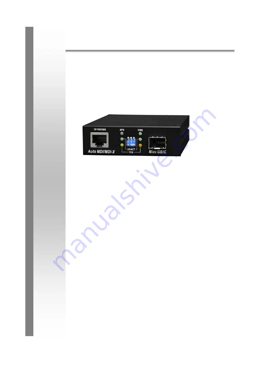
Page 10: ...rter module consists of one Giga Fiber port one copper Port Auto MDI MDIX and 6 LED Indicators SPD LK ACT FDX Fiber LK ACT FDX COL and PWR 1 RJ 45 Port 3 DIP Switch 2 LED 4 Fiber Connector Rear Panel...
Page 11: ...of fiber connectors SC SC single mode to meet your needs LED Indicators There are 6 diagnostic LEDs located on the Front panel of converter module They provide real time information of system and opt...
Page 12: ...nable OFF LLF Disable 2 ON Pure converter mode OFF Switch converter mode 3 ON Reserved OFF Reserved Link Lost Forwarding When LLF is enabled it will allow copper port link failure to be reported to th...
Page 13: ...Switch Converter mode off the converter function is same as Switch Hub Note a Please don t change the DIP switch setting when copper or fiber port is transmitting or receiving data It may cause some d...
Page 14: ...ar kit The kit contains two rack mount ear with thumbscrew and four screws C Attach rack mount ear on both sides of the modular converter by using a screwdriver to secure the rack mount ears D Install...
Page 15: ...Fiber segment using single mode connector type must use 9 125 m single mode fiber cable You can connect two devices in the distance of 10 Kilometers in full duplex operation For half duplex operation...
Page 16: ...etting in the same operation mode with the link partner Select the proper Copper Fiber cable to construct your network The single mode converter must use single mode fiber cable Please check that you...