


NCA-1526 User Manual
34
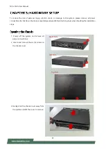
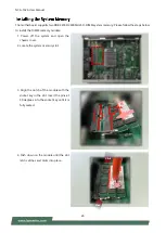
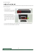
6.
Align the top power source pin to the
chassis rear opening spot, and insert the
bottom pins into JPOE connector pins.
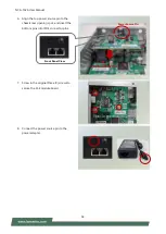
7.
Screw in the original three (3) screws to
secure the PoE module board.
8.
Connect the power source pin to the
power adapter.
Power Source Pin
JPOE Connector Pins
Front Panel View
Summary of Contents for NCA-1526
Page 14: ...NCA 1526 User Manual 14 ...
Page 40: ...NCA 1526 User Manual 40 ...
Page 53: ...NCA 1526 User Manual 53 ...
Page 60: ...NCA 1526 User Manual 60 ...