background image

22

Hardware Setup

Chapter 5

Embedded and Industrial Computing

External SIM Card Installation

Take out the SIM Card tray by pushing the ejector with 

1. 

a pointed object.
Place  the  SIM  card  on  the  SIM  card  tray.  Notice  the 

2. 

notch on the tray to prevent wrong orientation.

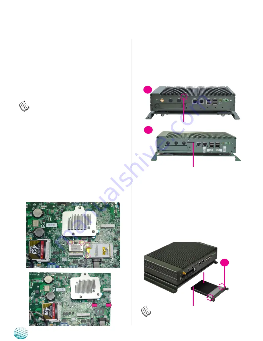
Hard Disk Installation

The system can accommodate one SATA hard drive. Follow 

these steps to install a hard disk into the system:

Place the HDD/SSD on the hard disk tray of the front 

1. 

panel  and  align  the  holes  of  the  hard  disk  with  the 

mounting holes on the tray.
Fix  the  HDD/SSD  on  the  hard  disk  tray  by  using  2 

2. 

mounting screws 
Push the HDD/SSD into the hard disk slot and secure it 

3. 

in place with the thumb screws attached on the tray.

Note:


The system only supports 2.5” HDD/SSD.

3G SIM Card Installation

Unlock  the  SIM  card  tray  by  sliding  it  outward  and 

1. 

open it.
Align the cut corner of the SIM card with the cut corner 

2. 

of the SIM card socket. Make sure the ICs is in contact 

with the socket.
Insert the 

3. 

SIM card into the tray diagonally. Close and 

lock the tray. You should feel a click when the SIM card 

is locked securely in the socket.

Note:


The system supports dual Internet connections 

1. 

with 2 SIM card reader. There are three MPCIE slot;  

MPCIE1 and MCARD1 slot support 3G SIM Card 

reader installation. MPCIE2 (Mini PCIe half card 

size) slot is for Wi-Fi or Bluetooth installation. For 

more information, see MPCIE1/MPCIE2/MCARD1 

on page 17 and 18.

We recommend the following 3G modules which 

2. 

are fully tested while designing of the system:

Sierra Wireless AirPrime™ MC MC809x series: These 
modules offer tri-band (850/1900/2100 MHz) or dual-band 
(900/2100 MHz) HSPA+ connectivity for roaming on high-
speed networks at speeds up to 14.4 Mbps downlink and 
up to 5.76 Mbps uplink, as well as quad-band GSM/GPRS/
EDGE and voice support.


Open

Close

1

ejector

front cover screw

1

2

Silver plate

Power Connector

Drive Connector

Summary of Contents for LVC-5550S

Page 1: ...In Vehicle Computing Hardware Platforms for Embedded and Industrial Computing LVC 5550S V1 1 User s Manual Publication date 2014 07 01...

Page 2: ...lity for its use nor for any infringements upon the rights of third parties that may result from such use Acknowledgement Intel Pentium and Celeron are registered trademarks of Intel Corp MicrosoftWin...

Page 3: ...Refer to MIL STD 810G Method 514 6 Procedure I Transportation Category 24 General minimal integrity Shock Operating Functional Test for Ground Equipment Refer to MIL STD 810G Method 516 6 Procedure I...

Page 4: ...hart 20 Chapter 5 Hardware Setup 21 Preparing the Hardware Installation 21 System Memory Installation 21 CompactFlash Card Installation 21 3G and Wireless Module Installation 21 3G SIM Card Installati...

Page 5: ...ptionarewellunder12V 12mA and 24V 10mA Extended operating temperature between 5 C 45 C 23 113 F System Specification Dimensions WxHxD 268x84x190mm 10 55 x3 31 x7 48 Processor Intel Atom D2550 Processo...

Page 6: ...audio internal cable optional P N 080W1C0901001 Drivers and User s Manual CD P N S09OAD826H100 Female Terminal Block Connectors P N 04AW20021E101 04AW20023Z101 04AW20031E001 04AW20161Z101 GPS Receiver...

Page 7: ...7 System Components Chapter 2 Embedded and Industrial Computing Chapter 2 System Components System Drawing Mechanical dimensions of the LVC 5550S with the suspension kit Unit mm...

Page 8: ...8 System Components Chapter 2 Embedded and Industrial Computing Block Diagram The block diagram depicts the relationships among the interfaces and modules on the motherboard...

Page 9: ...enabling or disabling the 3G SMS Ring wake up F3 Two 10 100 1000Mbps LAN ports Two RJ 45 network jacks with LED indicators as described below LINK ACT Yellow On Flashing The port is linking and active...

Page 10: ...witch connector Short Press Power off the system with the proper procedure just like the shutdown program on Windows Long Press Power off the system without the proper procedure i e force to shutdown...

Page 11: ...or projector resolution 1920x1200 VGA1 on page 17 R5 Line out and Mic in Port Connect audio devices to these port They are provided by Realtek ALC 886 HD audio codec AUDIO1 on page 16 R6 DIO Port The...

Page 12: ...yout External Connectors The following picture highlights the location of system input output connectors Refer to the table 3 1 Connector List for more details LANB2 LANB1 LED2 LED1 SIM1 RSTSW1 AUDIO1...

Page 13: ...ers The following picture highlights the location of internal connectors and jumpers Refer to the table 3 1 Connector List for more details MCARD1 SW2 SW5 3GAUDC1 CCMOS1 CF1 LVB 5550 CN2 SW3 SW4 PCOM1...

Page 14: ...3 P15 CON2 2 5 SATA HDD power connector P15 DC_IN1 9V 30V DC power in connector with ignition P16 DGIOC1 6bit Digital Input Output P16 DLPC1 LPC port 80 debugging port Reserved for factory use DVI1 D...

Page 15: ...S 232 RS 422 RS 485 1 DCD TxD Data 2 RXD TxD Data 3 TXD RxD 4 DTR RxD 5 GND Signal Ground 6 DSR 7 RTS 8 CTS 9 RI 5V 12V COM1 TYPE Description RS 232 Default 1 ON 2 OFF 3 OFF 4 OFF RS 422 1 OFF 2 ON 3...

Page 16: ...Input output pins DI_0 DI_1 DI_2 DI_3 DO_0 DO_1 DO_2 DO_3 Voltage Logic Register Di 0 8V Do 0 4V Low 0 DI 10 12V Do 12V High 1 DI_4 DI_5 only low status can be detected for MCU control 0 8V Low 0 3 3...

Page 17: ...LK 14 UIM_RESET 15 GND3 16 UIM_VPP KEY KEY 17 RSV3 18 Ground 19 RSV4 20 W_DISABLE 21 GND5 22 PERST 23 PERn0 24 3 3V 25 PERp0 26 Ground 27 Ground 28 1 5V 29 Ground 30 SMB_SLK 31 PETn0 32 SMB_DATA 33 PE...

Page 18: ...15 Ground 16 NC KEY KEY 17 NC 18 Ground 19 NC 20 W_DISABLE 21 GND 22 NC 23 NC 24 3 6V 3 3V 25 NC 26 Ground 27 Ground 28 NC 29 Ground 30 NC 31 NC 32 WAKE_N 33 RESET_N 34 Ground 35 Ground 36 USB_D 37 G...

Page 19: ...is a programmable function If there is no program to control and monitor the watchdog timer set this jumper to disabled to avoid abnormal shutdown Refer to the flow chart in Chapter 4 MCU Microcontro...

Page 20: ...od and low voltage 1 mechanism to function in the workflow you will need to enable the power good and low voltage detection function with selector 1 and selector 2 of jumper SW1 respectively of the LV...

Page 21: ...ystem Memory Installation The motherboard supports DDR3 memory to meet the higher bandwidth requirements of the latest operating system and Internet applications It comes with one DoubleDataRate DDR3...

Page 22: ...the cut corner of the SIM card with the cut corner 2 of the SIM card socket Make sure the ICs is in contact with the socket Insert the 3 SIM card into the tray diagonally Close and lock the tray You s...

Page 23: ...in connector comes with a 3 pin ter minal block for its Phoenix contact This power socket can only accept the power supply with the right pin contact so be cautious when inserting power to the system...

Page 24: ...m will start shutdown process automatically Refer to selector 2 of SW1 dip switch on the board Power on Delay min sec Select power on delay value to indicate the time to delay powering on the system R...

Page 25: ...s or control the operation of the G sensor GPS and Digital I O functions install the the L_ IO driver which is the library and driver needed for Lanner General Purpose Input Output interface or functi...

Page 26: ...ustrial Computing Choose to select the hardware Manually 8 Choose Show all device and click Next 9 Click HaveDisk to locate the L_IO inf file 10 Click HaveDisk to locate the L_IO inf file 11 Select th...

Page 27: ...ick 16 Complete to close the installation program To verify the GPIO driver installation do the following steps Right click on the My Computer icon and then select 1 Properties form the menu Click the...

Page 28: ...o h include stdlib h include unistd h if defined LINUX_ENV include sys io h endif if defined FreeBSD_ENV include machine cpufunc h endif include time h include stdint h include fcntl h include errno h...

Page 29: ...0x87 return void exit_SIO_config void outportb INDEX_PORT 0xAA return unsigned char read_SIO_reg int LDN int reg outportb INDEX_PORT 0x07 LDN register delay 5 outportb DATA_PORT LDN delay 5 outportb...

Page 30: ...fig return void dio_set_output unsigned char out_value enter_SIO_config write_SIO_reg 0x6 0xf1 read_SIO_reg 0x6 0xf1 0xF0 out_value exit_SIO_config return unsigned int dio_get_input void unsigned int...

Page 31: ...5Hz Horizontal position ac curach Autonomous 2 5m SBAS 2 0m Configurable Timepulse frequency range 0 1Hz to 1kHz Velocity accuracy 0 1m s Heading accuracy 0 5 degrees Operational Limits Dynamics less...

Page 32: ...Industrial Computing Select Add a new hardware device 7 Choose to select the hardware Manually 8 Choose to select the hardware Manually 9 Choose Show all device and click Next 10 Click HaveDisk to lo...

Page 33: ...14 Click Next 15 Click 16 Complete to close the installation program To verify the GPIO driver installation do the following steps Right click on the My Computer icon and then select 1 Properties for...

Page 34: ...PIO driver on your LVC 5550S as instructed in Appendix B and verify the serial ports have been detected Select Programs from the Start menu on your windows and open the Hyper Terminal program Choose C...

Page 35: ...35 Accessing the GPS Data Appendix C Embedded and Industrial Computing The hyper terminal should display GPS data...

Page 36: ...MI EXE should be placed on same directory then enter the values from 0 255 The system will reboot automatically according to the time out you set You can write your own program by modifying the source...

Page 37: ...rgument is numeric void CheckNumeric char szBuf int nLen strlen szBuf for int i 0 i nLen i if strchr 01234567890ABCDEFabcdef szBuf i throw Wrong argument n Common GPIO output function definition defin...

Page 38: ...t nPort atoi argv 2 BOOL ret Read_DIO nPort printf DIO_IN d d n nPort ret return ret Milli second delay int mSleep int argc char argv CHECK_ARGC 3 CheckNumeric argv 2 Sleep atoi argv 2 return 0 Watchd...

Page 39: ...eep mSleep Program start here int main int argc char argv try The total argument allowed int num sizeof c2f sizeof c2f 0 Too few argument if argc 2 RETMSG 1 PARAMETER_HELP Find the match argument and...

Page 40: ...ll be returned at customer s expense The following conditions are excluded from this 5 warranty Improper or inadequate maintenance by the customer Unauthorized modification misuse or reversed engineer...

Page 41: ...ing by Air Freight Sea Express ___ Others ________________ Item Model Name Serial Number Configuration Item Problem Code Failure Status Problem Code 01 D O A 02 Second Time R M A 03 CMOS Data Lost 04...

Reviews: