FX-3420 User Manual
13
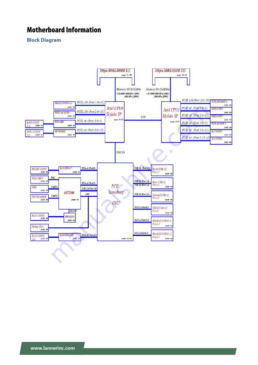
The block diagram indicates how data flows among components on the motherboard. Please refer to the following figure for your motherboard
’
s layout design.
Page 1: ...FX 3420 User Manual Version 1 0 Date of Release 2022 09 22 Network Appliance Platform...
Page 2: ...is something you should pay special attention to while using the product This mark indicates that there is a caution or warning and it is something that could damage your property or product To obtai...
Page 3: ...Town Changping District Beijing 102208 China T 86 010 82795600 F 86 010 62963250 E service ls china com cn USA Lanner Electronics Inc 47790 Westinghouse Drive Fremont CA 94539 T 1 855 852 6637 F 1 510...
Page 4: ...to radio communications However there is no guarantee that interference will not occur in a particular installation If this equipment does cause harmful interference to radio or television reception w...
Page 5: ...n incorrect type Dispose of used batteries according to the instructions Installation only by a skilled person who knows all Installation and Device Specifications which are to be applied Do not carry...
Page 6: ...ake for taking chilled air and exhaust for emitting hot air openings so that the amount of airflow required for safe operation of the equipment is not compromised To avoid a hazardous load condition b...
Page 7: ...ontre les effets n fastes du bruit externe et r duire les risques d lectrocution en cas de foudre Pour d sinstaller l quipement d branchez le c ble de mise la terre apr s avoir teint l appareil Un c b...
Page 8: ...tem Specifications 10 Front Panel 11 Rear Panel 12 Motherboard Information 13 Opening the Chassis 23 Installing the System Memory 23 Mounting the System 25 Installing the AC Power Supply 26 Remote Ser...
Page 9: ...g software defined storage platforms and HPC server where performance and storage are critical 2U High Performance Hyper converged Appliance Support Dual 2nd Gen Intel Xeon Scalable SP processor famil...
Page 10: ...t USB Port 2x USB 2 0 and 2 x USB 3 0 Ports at rear Serial COM Port 2x Serial COM Ports Display Port 1x DB 15 VGA Port Power Input AC Power Inlet on PSU Storage HDD SSD Support Front 12x 3 5 HDD SATA...
Page 11: ...ts 2x USB 2 0 ports F3 HDD Bay 12x 3 5 Swappable HDD Bays F4 LED Indicators F1 F2 F4 F3 A System Power B Show ID Button C Reset Button D System Failure LED E Memory Failure LED F FAN Failure LED G Pow...
Page 12: ...ize Card At Rear HHHL 2 x PCI E x16 slot Full Height Length 266 7 mm Standard Length is 312mm R4 COM Port 1x D sub COM1 port 1x reserved COM2 internal pin header R5 MGMT Port 1x Management RJ 45 port...
Page 13: ...FX 3420 User Manual 13 The block diagram indicates how data flows among components on the motherboard Please refer to the following figure for your motherboard s layout design...
Page 14: ...e jumper down on them so that they become SHORT To make the pins setting OPEN simply remove the jumper cap 2 pin Header 3 pin Header 4 pin Header Open Short Open 1 2 Jumped Open 1 2 Jumped 1 JDUAL1 1s...
Page 15: ...select Jumper Description 1 2 Hardware reset 2 3 Default Software reset 7 JBZ1 Buzzer function Jumper Description 1 2 Default Normal NC No buzzer function 8 JDTRIP1 CPU1 DIMM event Jumper Description...
Page 16: ...D 17 BMC_MEM_FAIL 18 BMC_UUID_BUT 19 GND 20 GND 21 BMC_FAN_FAIL 22 BMC_UUID_LED 23 GND 24 GND 25 BMC_PWR_FAIL 26 BMC_SYSF_BUT 27 GND 28 GND 29 BMC_TRM_FAIL 30 LAN_LINK_ACT 2 FPC2 Front I O board Conne...
Page 17: ...GND 30 GND 3 J1 LC4064ZE JTAG Pin no Description Pin no Description 1 P1V8LC 5 NC 2 TDO_4032 6 TMS_4032 3 TDI_4032 7 GND 4 NC 8 TCK_4032 4 J80P1 Debug 80 port Pin no Description Pin no Description 1 C...
Page 18: ...7 BMC_COM2_DTR 8 BMC_COM2_RI 9 COM2_GND 10 NC 6 JDB1 BMC UART5 port Pin no Description 1 P3V3_AUX 2 UART_RXD5 3 GND 4 UART_TXD5 7 JPMB1 Power management connector Pin no Description Pin no Description...
Page 19: ...PI_PCH_IO3 7 NC 8 SPI_CLK 9 GND 10 SPI_MOSI 10 JTPM1 TPM Pin Header Pin no Description Pin no Description 1 IRQ_SERIAL 2 LPC_LFRAME 3 LPC_LAD0 4 CLK_24M_LPC 5 LPC_LAD1 6 P3V3_AUX 7 LPC_LAD2 8 NC 9 LPC...
Page 20: ...o Description A1 CLK_PCIE_U2_x_P B1 U2_RST C1 U 2_LED1_N D1 SMB_3V3_DAT A2 CLK_PCIE_U2_x_N B2 GND C2 NC D2 SMB_3V3_CLK A3 GND B3 GND C3 GND D3 GND A4 PCIE_U2_RX_P1 B4 PCIE_U2_RX_P0 C4 PCIE_U2_TX_P1 D4...
Page 21: ...ATA_TX_P2 A8 PSATA_RX_N3 B8 PSATA_RX_N2 C8 PSATA_TX_N3 D8 PSATA_TX_N2 A9 GND B9 GND C9 GND D9 GND 15 JSASHD3 SSATA connector Pin no Description Pin no Description Pin no Description Pin no Description...
Page 22: ...no Description 1 GND 3 P12V 2 BMC_PWMOUT 4 BMC_FAN_TECH_IN 17 JFAN7 JFAN10 FAN connector Pin no Description Pin no Description 1 GND 4 BMC_FAN_TECH_IN 2 P12V 5 BMC_PWMOUT 3 BMC_FAN_TECH_IN 18 JPWR2 Po...
Page 23: ...Gently pull the cover backward a bit and lift the cover up to remove it 3 Remove the cover that encloses the CPUs and the fans The motherboard supports 24 memory slots for DDR4 registered DIMM Total S...
Page 24: ...are highly recommended However with mixed module speeds the overall speed will be that of the slowest installed memory module Please follow the steps below to install the DIMM memory modules 1 Power o...
Page 25: ...cket assembly alone cannot provide sufficient support to the chassis Please ensure the use of these brackets goes with a shelf or slide rails to prevent the chassis from falling over Slide Rail Kit Sh...
Page 26: ...ly Please be noted that this system supports only 850W PSU Please prepare the power supply units matching this capacity 1 On the rear panel locate the power supply units and disconnect the power cords...
Page 27: ...ort KCS System Interface Support LAN RMCP IPMI 2 0 based Management BMC stack with an IPMI 2 0 implementation System Management Sensor monitoring System power management Watchdog timer Fan speed monit...
Page 28: ...power reset Chassis power soft Server s power status report Watchdog Timer The BMC provides an IPMI 2 0 compatible watchdog timer which can prevent the system from system hanging Fan Speed Control BMC...
Page 29: ...inistrator Moreover the account creator is allowed to enable disable the user account at any time If not specified the default user accounts are listed follows User Name Password User Access Character...
Page 30: ...es Chassis 00h 00h Get Chassis Status Chassis 00h 01h Chassis Control Chassis 00h 02h Chassis Reset Chassis 00h 03h Sensor Device Commands Get Sensor Reading Factors S E 04h 23h Get Sensor Hysteresis...
Page 31: ...Offset Storage 0Ah 5Dh LAN Device Commands Set LAN Configuration Parameters Transport 0Ch 01h Get LAN Configuration Parameters Transport 0Ch 02h Serial Modem Device Commands Set User Callback Options...
Page 32: ...ou to enter username and password A screenshot of the login screen is given below Login Page Username Enter your username in this field Password Enter your password in this field Sign me in After ente...
Page 33: ...og in The dialog is shown below Change the default password Dialog Clicking OK will take you to the User Management Configuration page to set a password Change the default password Set password Note D...
Page 34: ...UI consists of various menu items Menu Bar The menu bar displays the following Dashboard Sensor Event Log Settings Remote Control Image Redirection Power Control Maintenance Sign out A screenshot of t...
Page 35: ...tions Notification Click the icon to view the notification messages Refresh Click the icon to reload the current page Sign out Click the icon to log out of the Web UI This option shows the logged in u...
Page 36: ...d make a bootable DVD from it 2 Connect a DVD player or other type of readers floppy disk or a drive to a computer 3 Connect to your target system from this computer Refer to Remote Server Management...
Page 37: ...fter a JViewer screen pops up select Media and then Virtual Media Wizard from the toolbar 6 On Virtual Media screen select your media type to load the image For example click on Browse of CD DVD Media...
Page 38: ...8 7 The Status window will display the connection status 8 The installation process will automatically start Please follow the onscreen instruction to complete the rest of the steps and restart the ta...
Page 39: ...the system 2 Pressing the Tab or Del key immediately allows you to enter the Setup utility and then you will be directed to the BIOS main screen The instructions for BIOS navigations are as below Cont...
Page 40: ...s Solid Green Operating as a 100 Mbps connection Off Operating as a 10 Mbps connection Link Activity Blinking Green Link has been established and there is activity on this port Solid Green Link has be...
Page 41: ...iderable time and effort but all you work might also be to no avail Eventually you are left with no choice but to ship the board back to the manufacturer Lanner understands this pain and has empowered...
Page 42: ...onto the motherboard carrying two separate BIOS images The Primary BIOS carries the image for system bootup the parameters of which can be overwritten while the Recovery BIOS carries the image locked...
Page 43: ...BIOS used for this bootup With the Recovery BIOS at work it can be asserted that the Primary BIOS is having such severe problem that it failed to function Before you make certain the BIOS chip is com...
Page 44: ...you select the correct firmware version and go through the instructions for BIOS update in BIOS Engineering Spec and BIOS fix information in the Release Note thoroughly If you cannot be certain if th...
Page 45: ...pense 5 The following conditions are excluded from this warranty Improper or inadequate maintenance by the customer Unauthorized modification misuse or reversed engineering of the product Operation ou...
Page 46: ...FX 3420 User Manual 46 When requesting RMA service please fill out the following form Without this form enclosed your RMA cannot be processed...