LANIER
– 1.20 Edge 540T ARF -
INSTRUCTIONS
BUILDING INSTRUCTIONS
Before starting to build this kit, we urge you to read
through these instructions thoroughly. They contain
some important building sequences as well as
instructions and warnings concerning the assembly
and use of the model.
BUILDING SUPPLIES NEEDED
Hobby knife w/ #11 blade
Medium Zap CA
30 Minute Z-poxy
Wire cutters
Pliers
Drill with bits: 1/32”, 1/16”, 1/8”, 5/32”, ¼”
See the list at the end of the instruction book for a
list of additional R/C equipment you will need to
complete the 1.20 Edge 540.
1.
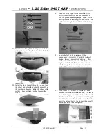
Locate (8) hinges.
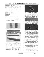
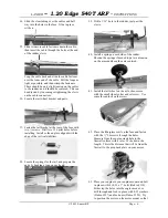
2. Use the picture as a guide to find the (4) holes in
each aileron and each side of the wing. Test fit a
hinge in each hole.
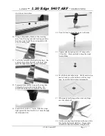
3. Put a small drop of oil on each hinge, then use 30
minute epoxy on each hinge and hole. Press the
ailerons in place, leaving a 1/32” gap at the hinge
line, then wipe off any excess epoxy off with
alcohol and a paper towel.
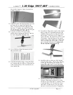
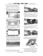
4. At the two locations on the wing, remove the
covering from the hole to install your aileron
servo. Check the hole for the servo wires. If
needed, use a piece of 3/8 or ½” brass tube to cut
a passage for the wire to the servo opening.
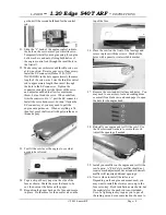
5. Install your aileron servo with the hardware
included with your radio. You may need to
enlarge the hole in the wing with a file or small
saw, depending on the size of the servo you use.
Drill a small pilot hole (1/32”) for each screw.
Hook the servo to your radio and turn it on. Set
the trim tabs to neutral and center the servo.
6. Locate the (2) 8” long 2-56 rods, (2) clevis, (2)
couplers, (2) washers, and (2) 3 x 40mm Philips
screws. Install a clevis on the end of each rod.
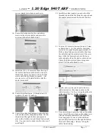
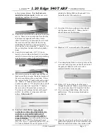
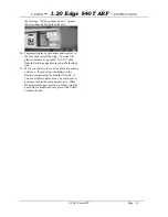
7. Install a (4) arm servo wheel on the servo
temporarily, making sure it is parallel to the
wing. Locate the hard points in the ailerons, and
pierce the covering with a sharp hobby blade.
Install the (2) aileron control horn screws from
the top of the wing, down through the aileron.
Secure the bolt with a washer, nut, and thread
lock. Install the (2) couplers on the control horn
bolts until the threads just show from the tops.
Hook the links to the aileron couplers and lay the
rods across the servo arm.
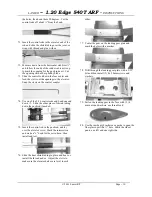
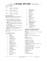
8. Mark the location of the servo arm holes on the
control rods. This is the location for the “z”
bend on the each control rod. Make a “z” bend
on each control rod with needle nose pliers or
“z” bend pliers, then cut off the excess control
rod. Install the “z” bend on the servo arm, at the
same hole on each arm. You may need to
enlarge the hole with a small drill bit. Cut off
the (3) extra arms with wire cutters.
9. Check again that the servo is centered with your
radio, then reinstall the servo horn and screw it
in place. If the ailerons are not level, disconnect
the links and adjust them until they are level.
Place a short piece of fuel tubing around each
© 2001 Lanier R/C
Page - 2


