background image


20


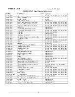
PARTS LIST 

October 29, 2007, Rev D


236S-NAT/LP Gas Griddle Selectronic 

PART # 

DESCRIPTION 

QTY  Application 

2A-72500-02 

Legs 

236S-LP, NAT, CHG-NAT, HG236SC1LNAT 

2A-80401-02 

Orifice, Pilot Burner LP .010 

236S-LP 

2A-80401-03 

ORFICE, PILOT LP 

236S-LP 

2A-80401-05 

PILOT BURNER ORFICE  

HG236SC1LNAT 

2E-30303-06 

Switch, Toggle On-ON DPDT Black Metal 

236S-LP, NAT, CHG-NAT, HG236SC1LNAT 

2E-30303-18 

SWITCH, TOGGLE ON/OFF, 12" section 

236S-LP, NAT, CHG-NAT, HG236SC1LNAT 

2E-30304-22 

Temperature Selector Switch 175°-450°F 

236S-LP, NAT, CHG-NAT, HG236SC1LNAT 

2E-30308-01 AIR 

SWITCH 

HG236SC1LNAT 

2E-30501-02 

Terminal Strip, 3 Pole w/push on Trim 

HG236SC1LNAT 

2E-30501-03 

Terminal Strip, 4 Pole w/push on Trim 

236S-LP, NAT, CHG-NAT, HG236SC1LNAT 

2E-31107-02 

CORD SET 

236S-LP, NAT, CHG-NAT 

2E-31107-06 CORD 

SET 

HG236SC1LNAT 

2E-31400-07 

Transformer, 115/24 Volt 

236S-LP, NAT, CHG-NAT 

2E-40101-19 

Circuit Board, Temperature Control, no offset 

236S-LP, NAT, CHG-NAT, HG236SC1LNAT 

2E-40704-04 CAP-BLOWER 

START 

HG236SC1LNAT 

2E-41100-26-2 

SENSOR 

236S-LP, NAT, CHG-NAT, HG236SC1LNAT 

2F-50404-51 

PLATE 

236S-LP, NAT, HG236SC1LNAT 

2F-50407-26 Grid 

plate 

236SCHG-NAT 

2J-31601-07 

Pilot Light, 250V 6” Lead WHITE Body 

236S-LP, NAT, CHG-NAT, HG236SC1LNAT 

2J-80201-24 

Pilot Burner, Sections 2, 3 

236S-LP, NAT, CHG-NAT, HG236SC1LNAT 

2J-80201-25 

Pilot Burner, Sections 1  

236S-LP, NAT, CHG-NAT, HG236SC1LNAT 

2J-80300-03 

Ignition Module 

236S-LP, NAT, CHG-NAT, HG236SC1LNAT 

2J-80300-10 

SPARK IGNITION CONTROL 

HG236SC1LNAT 

2J-80302-06 IGNITOR/SENSOR 

CHANNEL 

HG236SC1LNAT 

2Q-103-122 HANDLE 

GRIP 

HG236SC1LNAT 

2R-103-73 HANDLE 

HG236SC1LNAT 

2R-70701-28 

Knob, Temperature Control 

236S-LP, NAT, CHG-NAT, HG236SC1LNAT 

2U-30200-44 

MOTOR AND BLOWER ASSY 

HG236SC1LNAT 

2V-80501-04 

Regulator, Gas Set 5” NG Griddle ¾” X ¾” 

236S-NAT, CHG-NAT 

2V-80501-05 

Regulator, Gas Set 10” LP Griddle ¾” X ¾” 

236S-LP 

2V-80501-07 

Regulator, Spring Conversion Kit NG to LP 

236S-NAT, CHG-NAT, HG236SC1LNAT 

2V-80501-10 REGULATOR- 

HG236SC1LNAT 

2V-80502-03 

Valve, Solenoid 24 VAC, ½” Pipe 

236S-LP, NAT, CHG-NAT 

2V-80506-01 

Flame Switch 24” Capillary 

236S-LP, NAT, CHG-NAT, HG236SC1LNAT 

K9-80002-09 

Main Burner 

236S-LP, NAT, CHG-NAT, HG236SC1LNAT 

K9-EZG-339 

Grease Drawer 2 

236S-LP, NAT, CHG-NAT, HG236SC1LNAT 

PS-JIB-SEN-SEL 

Kit, Probe, Select G 

236S-LP, NAT, CHG-NAT, HG236SC1LNAT 

Y9-80400-11 

Orifice, Main Burner NG .0935 #42 Drill 

236S-NAT, CHG-NAT 

Y9-80400-12 

Orifice, Main Burner LP .0595 #53 Drill 

236S-LP 

Y9-80400-26 

ORFICE, PILOT LP 

HG236SC1LNAT 

2E-31400-07 

Transformer, 115/24 Volt 

HG236SC1LNAT 

2V-80502-03 

Valve, Solenoid 24 VAC, ½” Pipe 

HG236SC1LNAT 


Summary of Contents for SELECTRONIC

Page 1: ... Louis MO 63143 3800 Part Number 2M W360 Ph 314 781 2777 Fax 314 781 2714 Rev D WWW STAR MFG COM October 29 2007 1 Installation Operation and Maintenance Instructions Gas Griddle Spark Ignition SELECTRONIC Models 224S 236S 236SCHG CHROME 248S 260S 272S ...

Page 2: ... GAS INSTALLATION CODE OR CAN CGA B149 2 PROPANE INSTALLATION CODE AND LOCAL CODES WHERE APPLICABLE FOR YOUR SAFETY DO NOT STORE OR USE GASOLINE OR OTHER FLAMMABLE VAPORS AND LIQUIDS IN THE VICINITY OF THIS OR ANY OTHER APPLIANCE POST IN A PROMINENT LOCATION WARNING IMPROPER INSTALLATION ADJUSTMENT ALTERATION SERVICE OR MAINTENANCE CAN CAUSE PROPERTY DAMAGE INJURY OR DEATH READ THE INSTALLATION OP...

Page 3: ...TENTS 3 2 READ FIRST 4 3 EQUIPMENT DESCRIPTION 6 4 UNPACKING 8 5 INSTALLATION 9 6 INITIAL START UP 11 7 OPERATION 12 8 SEQUENCE OF OPERATION 15 9 MAINTENANCE CLEANING PROCEDURES 16 10 TROUBLESHOOTING 17 18 11 PARTS LISTS 19 25 12 WIRING DIAGRAMS 27 ...

Page 4: ...N ACCORDANCE WITH ALL APPLICABLE CODES NOTICE The data plate is located inside the control compartment of each griddle The griddle voltage serial number gas specifications and clearance specifications are on the data plate This information should be carefully read and understood before proceeding with the installation NOTICE The installation of this griddle must conform to applicable National Stat...

Page 5: ...a chlorine sanitizer in contact with stainless steel surfaces longer than 10 minutes Longer contact can cause corrosion NOTICE Service on this or any other LANG appliance must be performed by qualified personnel only Consult your LANG authorized service agent directory or call the factory at 1 800 807 9054 or WWW STAR MFG COM For the service agent nearest you WARNING BOTH HIGH AND LOW VOLTAGES ARE...

Page 6: ...ck in any temperature from 175 F to 450 F in 25 increments Each twelve inch section of the griddle is controlled by an area sensitive RTD probe which can sense and react to a temperature change of 4 F 3 3 Controls The SELECTRONIC Griddle comes with the solid state controls which include An on standby switch for the entire unit Temperature selector switches for each twelve inch section 3 4 Technica...

Page 7: ...T 2 SUPPLIED 272S 72 INCHES 162 000 162 000 TWO 3 4 NPT 115 VOLT 2 SUPPLIED SPECIFICATIONS AND INFORMATION GRILL SURFACE OVERALL CLEARANCE FROM COMBUSTIBLE SURFACES MODEL NUMBER WIDTH DEPTH SQUARE INCHES OF GRIDDLE NUMBER OF BURNERS NUMBER OF CONTROLS NUMBER OF GREASE DRAWERS SIDES BACK BOTTOM SHIPPING WEIGHT 224S 24 INCHES 23 INCHES 552 2 2 1 5 INCHES 5 INCHES 4 INCH LEG 260 236S 36 INCHES 23 INC...

Page 8: ... near its intended location as practical The crating will help protect the unit from the physical damage normally associated with moving it through hallways and doorways 4 3 Un crating The griddle will arrive completely assembled inside a wood frame covered by cardboard box and strapped to a skid Remove the cardboard cover cut the straps and remove the wood frame Remove griddle from skid and place...

Page 9: ... with the griddle Follow the receptacle manufacturer s instructions when connecting the receptacle to the power supply 5 2 Gas Connection This griddle is manufactured for use with the type of gas indicted on the nameplate Contact the factory if your type of gas does not match the nameplate data All gas connectors must be in accordance with local codes and comply with the National Fuel Federal Gas ...

Page 10: ...hould be used that is resistant to the action of liquid petroleum gas Initial adjustments are the responsibility of the installer and are not chargeable to Star Manufacturing International After the griddle is in its final position adjust the legs to create 1 8 inch slant from back to front This will allow the grease to run into the grease gutter and provide the proper combustion air for the burne...

Page 11: ...rn the main toggle switch to STANDBY 6 2 Seasoning the Griddle Plate non chrome only Set the temperature dials to 300 F 148 C Observe the burners through the opening at the top of the control panel When the burners go OFF apply a thin coat of high grade non salted vegetable oil to the griddle surface Rub the oil into the griddle surface with the flat side of a spatula or a towel Recoat any dry spo...

Page 12: ...ium 375 F 190 C 5 to 7 3 4 to 1 inch thick cooked medium 375 F 190 C 8 to 10 Lamb Chops 350 F 176 C 6 to 8 Pork Chops 350 F 176 C 6 to 8 Salmon 350 F 176 C 6 to 8 Halibut 325 F 162 C 6 to 8 Snapper 325 F 162 C 6 to 8 Hashbrown Potatoes 375 F 190 C 3 to 4 Bacon 350 F 176 C 3 to 4 Sausage Links or Patties 350 F 176 C 3 to 4 Ham Pre cooked 375 F 190 C 2 Eggs 275 F 135 C 2 to 4 Note The times and temp...

Page 13: ...e entire cooking section If the product is loaded to the side front or back of the temperature sensor the thermostat will react to the temperature change much slowly During slow periods with minimal loads do not load directly over the thermostat sensors as this will unnecessarily turn the burners on and overheat the remainder of the section not being utilized Turn the product and continue cooking ...

Page 14: ...o the circuit board for that section The operator can now set the temperature of that section by selecting it on the temperature dial When the temperature on the dial is set higher than the temperature of the griddle section the circuit board will generate a Heat call This call 24 VAC Signal goes to the solenoid valve opening the valve The pilot burner ignites the main burner As the griddle sectio...

Page 15: ...sh guard Chrome griddle surfaces can be scraped with a 4 wide Razor Sharp scrapper and wipe surface with a damp cloth Following the scraping a damp cloth and non silicated non abrasive non chlorinated cleaner such as Bon Ami may be used to wipe surface clean followed by wiping with a clean wet cloth 9 2 Weekly Cleaning Non chrome only A mild detergent with water or one of the many commercial clean...

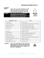
Page 16: ...vent Failed transformer Power indicator is not lit No power to cord outlet Griddle unplugged from outlet Failed power cord or plug Failed power switch Failed pilot light Section will not heat Failed gas valve Failed spark module Failed circuit board Failed temperature sensor Plugged pilot orifice Product burning Product is cooked too long Failed temperature sensor Failed circuit board Failed tempe...

Page 17: ...r switch Check switch for continuity across poles Failed pilot light Check for continuity across pilot light leads Failed gas valve Remove the wires from the valve terminals and check for continuity across the coil Failed igniter Replace as necessary Failed spark module Check for correct incoming voltage at module Failed circuit board Check for proper voltage and operation Failed temperature senso...

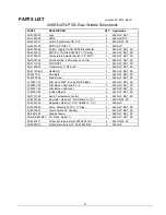
Page 18: ...trol no offset 2 224S NAT 2E 41100 26 2 SENSOR 2 224S NAT 2F 50407 25 Grid plate 1 224S NAT 2J 31601 07 Pilot Light 250V 6 Lead WHITE Body 1 224S NAT 2J 80201 24 Pilot Burner Sections 2 1 224S NAT 2J 80201 25 Pilot Burner Sections 1 1 224S NAT 2J 80300 03 Ignition Module 2 224S NAT 2R 70701 28 Knob Temperature Control 2 224S NAT 2V 80501 04 Regulator Gas Set 5 NG Griddle X 1 224S NAT 2V 80501 07 R...

Page 19: ... Body 1 236S LP NAT CHG NAT HG236SC1LNAT 2J 80201 24 Pilot Burner Sections 2 3 2 236S LP NAT CHG NAT HG236SC1LNAT 2J 80201 25 Pilot Burner Sections 1 1 236S LP NAT CHG NAT HG236SC1LNAT 2J 80300 03 Ignition Module 3 236S LP NAT CHG NAT HG236SC1LNAT 2J 80300 10 SPARK IGNITION CONTROL 1 HG236SC1LNAT 2J 80302 06 IGNITOR SENSOR CHANNEL 1 HG236SC1LNAT 2Q 103 122 HANDLE GRIP 1 HG236SC1LNAT 2R 103 73 HAND...

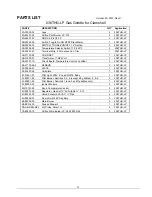
Page 20: ...mperature Control no offset 3 236THG LP 2E 41100 26 2 SENSOR 3 236THG LP 2F 50404 51 PLATE 1 236THG LP 2F 50407 26 Grid plate 1 236THG LP 2J 31601 07 Pilot Light 250V 6 Lead WHITE Body 1 236THG LP 2J 80201 24 Pilot Burner Sections 2 3 4 except 6ft griddles 5 6 2 236THG LP 2J 80201 25 Pilot Burner Sections 1 and 4 on 6ft griddles only 1 236THG LP 2J 80300 03 Ignition Module 3 236THG LP 2R 70701 28 ...

Page 21: ...26 2 SENSOR 4 248S LP NAT SC 2F 50407 27 Grid plate 1 248S LP NAT SC 2F 80002 09 Main Burner 4 248S LP NAT SC 2J 31601 07 Pilot Light 250V 6 Lead WHITE Body 1 248S LP NAT SC 2J 80201 24 Pilot Burner Sections 2 3 4 3 248S LP NAT SC 2J 80201 25 Pilot Burner Sections 1 1 248S LP NAT SC 2J 80300 03 Ignition Module 4 248S LP NAT SC 2R 70701 28 Knob Temperature Control 4 248S LP NAT SC 2V 80501 04 Regul...

Page 22: ...6 2 SENSOR 5 260S LP NAT SC 2F 50407 28 Grid plate 1 260S LP NAT SC 2F 80002 09 Main Burner 5 260S LP NAT SC 2J 31601 07 Pilot Light 250V 6 Lead WHITE Body 1 260S LP NAT SC 2J 80201 24 Pilot Burner Sections 2 3 4 5 4 260S LP NAT SC 2J 80201 25 Pilot Burner Sections 1 1 260S LP NAT SC 2J 80300 03 Ignition Module 5 260S LP NAT SC 2R 70701 28 Knob Temperature Control 5 260S LP NAT SC 2V 80501 04 Regu...

Page 23: ...t 6 ALL 2E 41100 26 2 SENSOR 6 ALL 2F 50407 29 Grid plate 1 ALL 2F 80002 09 Main Burner 6 ALL 2J 31601 07 Pilot Light 250V 6 Lead WHITE Body 1 ALL 2J 80201 24 Pilot Burner Sections 2 3 4 except 6ft griddles 5 6 4 ALL 2J 80201 25 Pilot Burner Sections 1 and 4 on 6ft griddles only 2 ALL 2J 80300 03 Ignition Module 6 ALL 2R 70701 28 Knob Temperature Control 6 ALL 2V 80501 04 Regulator Gas Set 5 NG Gr...

Page 24: ... FLAME SWITCH FLAME SWITCH FLAME SWITCH FLAME SWITCH BURNER VALVE BURNER VALVE BURNER VALVE BURNER VALVE TEMPERATURE CONTROL BOARD TEMPERATURE CONTROL BOARD TEMPERATURE CONTROL BOARD TEMPERATURE CONTROL BOARD 12 POSITION SWITCH 12 POSITION SWITCH 12 POSITION SWITCH 12 POSITION SWITCH RTD RTD RTD RTD 34 WHT 47 WHT 60 WHT 73 WHT 33 BLK 46 BLK 59 BLK 72 BLK N N N N G G G G L L L L 22 GRN 35 GRN 48 GR...

Reviews:

Related manuals for SELECTRONIC