Assembly Instruction
Positioning SystemLHT500 - 100 x 50
Assembly Instruction - TranslationDoc - ID: 782330:027.26.MA-ENG-V1.1
Read Instruction before start working!
Page 1: ...Assembly Instruction Positioning System LHT500 100 x 50 Assembly Instruction Translation Doc ID 782330 027 26 MA ENG V1 1 Read Instruction before start working...
Page 2: ...2 30 11 12 Lang GmbH Co KG Dillstra e 4 35625 H ttenberg Tel 49 0 6403 7009 0 Fax 49 0 6403 7009 40 E Mail info lang de Internet www lang de...
Page 3: ...y Rules 14 2 5 Safety Devices 14 2 6 Customer Responsibilities 15 2 7 Personnel Requirements 16 2 8 Personal Protective Equipment 18 2 9 Signs 19 3 Technical Data 20 3 1 Dimensions and Weight 20 3 2 O...
Page 4: ...y Instructions for Assembly 31 6 2 Overview 33 6 3 Flatness Requirements 33 6 4 Tightening Torques 33 6 5 Mounting Options 34 6 6 Preparations 34 6 7 Required Tools 36 6 8 Remove Transport Locking 36...
Page 5: ...tions 46 9 3 Required Tools 48 9 4 Disassembly of Electrical Connectors 48 9 5 Insert Transport Locking 49 10 Troubleshooting 50 10 1 Troubleshooting Table 50 11 Disassembly and Disposal 52 11 1 Safet...
Page 6: ...ork safety and accident control for the application area of the positioning system When selling the positioning system provide the assembly instruction Figures in this instruction are for general unde...
Page 7: ...ns must also reference a RMA Number Fill in the failure description as detailed as possible On inspection of the positioning system by Lang technicans the customer will receive a cost estimate before...
Page 8: ...Instructions Safety instructions are marked by symbols and where initiated by signal words which describes the type of harm DANGER indicates an imminently hazardous situation which if not avoided wil...
Page 9: ...E indicates information or a company policy that relates directly or indirectly to the safety of personnel or protection of property CAUTION indicates an imminently hazardous situation by electrical h...
Page 10: ...ely designed for the incorporation in a machine The positioning system is made to position payloads under the specified terms Intended use also includes observance of all stated instructions provided...
Page 11: ...the following listed residual risks resulting from the positioning system during its intended use 2 3 1 Mechanical Hazards Crushing Hazard WARNING Moving parts can crush Contact with moving parts coul...
Page 12: ...njury by electric shock All operations at electrical installations shall only be executed by experienced and qualified personnel Follow the 5 safety rules according to chapter Safety 2 4 before start...
Page 13: ...lt in significant damage Set parameters only in accordance to the specified terms NOTICE Risk of environmental damage caused by incorrect handling of hazardous substances Improper handling of hazardou...
Page 14: ...nt closing of the isolating switches Test absence of voltage Earthing and short circuting Protect adjacent live parts by covers and barriers and fit a suitable warning notice 2 5 Safety Devices WARNIN...
Page 15: ...his assembly instruction Especially important is as follows The customer is responsible to observe applicable work safety regulations and identify possible causes of harm in a general risk assessment...
Page 16: ...ioning system requires different qualifications and knowledge Inadequat Qualification Any operation with the positioning system is reserved for reliable and skilled personnel WARNING Risk of injury ca...
Page 17: ...easures Qualified Electrician Qualified electrician is due to qualification knowledge of the relevant regulations and experience able to execute the assigned work at electrical installations probably...
Page 18: ...onal protective equipment in this assembly instruction is described as follows Wear protective working clothes Protective working clothes shall be tide fitting with low tensile strength tide sleeves a...
Page 19: ...Safety 30 11 12 19 2 9 Signs The positioning system is not fitted with signs...
Page 20: ...ter Value Unit Length 352 mm Width 268 mm Height 50 mm Weight 7 4 kg Parameter Value Unit Ambient temperature 20 C Temperature variation 0 5 C rel Humidity 45 5 Dust exposure acc ISO 14644 1 Classifi...
Page 21: ...Ball Screw Parameter Value Unit Ambient temperature 10 70 C Temperature variation C rel Humidity 45 5 Dust exposure acc ISO 14644 1 Classifi cation Parameter Value Unit Fz 500 N Parameter Value Unit...
Page 22: ...ct hall switches low active low side switch pull up resistor 5 6 k 3 7 1 Switching Characteristic Parameter Value Unit Travel X axis Y axis 100 50 mm mm Repeatability 1 m Parameter Value Unit Nominal...
Page 23: ...116 3 9 Electrical Connectors Flange plug 12 pin WARNING Risk of injury and property damage caused by operating errors Each positioning system has an own wiring diagram Use only the provided wiring di...
Page 24: ...gnment D Sub 15 pin male 3 11 Sound Level The continuous sound level is not higher than 70 db A 3 12 Degree of Protection The positioning system correspond to IP40 PIN Assignment A Vcc LS 5 24V B B C...
Page 25: ...ing Manufacturer lubricant Ball screw Greased by FMD FG Li 6 plus MoS2 PARALIQ P 460 Ball screw Relubrication PARALIQ P 460 NOTICE Risk of property damage caused by wrong lubrication The lubrication w...
Page 26: ...a 26 30 11 12 3 14 Label The label is at the terminal of the positioning system It contains the following information Name and address of manufacturer Type designation Year of manufacture Part number...
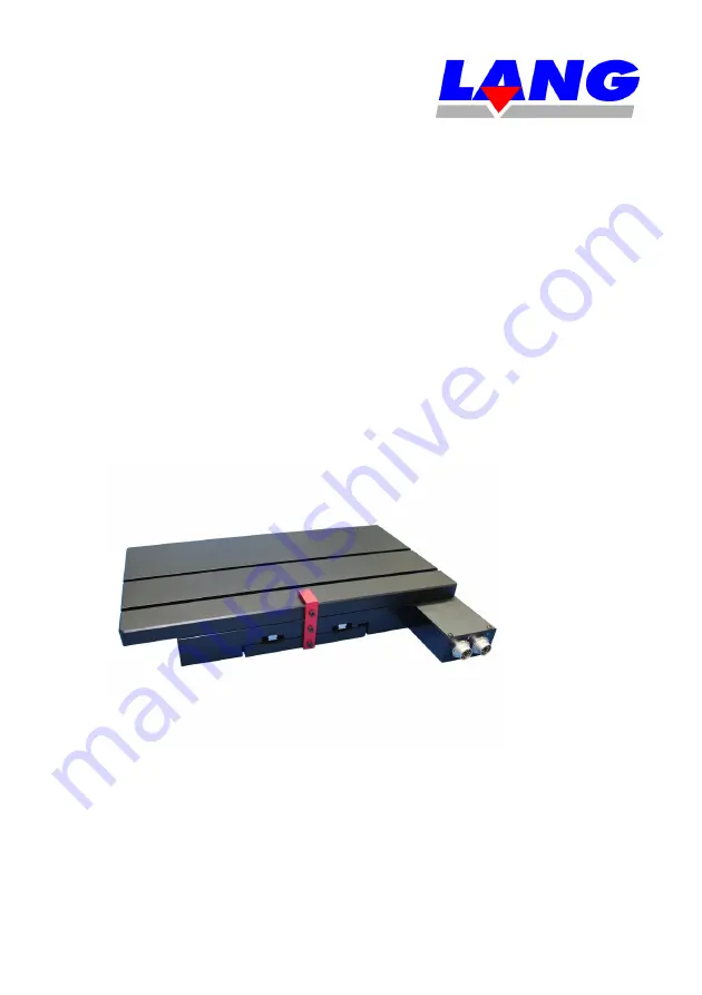
Page 27: ...Operation 30 11 12 27 4 Design and Mode of Operation 4 1 Overview and Coordinate System 1 Y axis bottom side 2 X axis 3 Terminal 4 2 Mode of Operation The positioning system allows the positioning alo...
Page 28: ...ompleteness and possible occured shipping damages 5 2 Safety Instructions for Transport Improper Transport NOTICE Risk of property damage caused by improper transport Improper transport may lead to si...
Page 29: ...rate during liability period Note design dimensions and form including the filling material and tagged safety signs before disposing the packaging For future transportation request original packaging...
Page 30: ...icable radiation and or hazardous substances directives before return NOTICE Risk of property damage caused by improper storage Improper storage may lead to significant damage Positioning system and e...
Page 31: ...ould lead to serious injury and or significant property damage All operations shall only be executed by experienced and qualified personnel Maintain a clean and tidy working area Loose parts component...
Page 32: ...fety shoes CAUTION Live parts can cause electric shock Contact with parts carrying electric current could result in injury by electric shock Follow the 5 safety rules according to chapter Safety 2 4 b...
Page 33: ...oning system should be mounted on a flat stable surface according to guideline GGG P 463c AA granite base with flatness grade of 000 according DIN 876 6 4 Tightening Torques Pay attention to the max t...
Page 34: ...with the installation conditions flatness requirements Compliance with the operating conditions according to the specifications made in chapter Technical Data Required documents are available Require...
Page 35: ...performance specifications are dependent on the following conditions Avoid deformations of the positioning system Avoid damaging the positioning system by fastening material and or customer equipment...
Page 36: ...t from shipping damage NOTICE Risk of property damage caused by improper cleaning Improper cleaning may lead to significant property damage Keep purifier free from live parts NOTICE Risk of property d...
Page 37: ...and customer equipment 1 Clean the mounting surface before assembly 2 Start tightening with centrally located screw joints tighten the outer screw joints at last 6 10 Fixing the Positioning System Bo...
Page 38: ...amage All operations shall only be executed by experienced and qualified personnel Ensure that all covers and safety devices are installed and fully functional The positioning system is fully function...
Page 39: ...ty shoes CAUTION Live parts can cause electric shock Contact with parts carrying electric current could result in injury by electric shock Follow the 5 safety rules according to chapter Safety 2 4 bef...
Page 40: ...alth and safety regulations NOTICE Risk of property damage caused by improper start up Electronic devices are sensitive against electrostatic discharge touching pins may lead to significant damage Do...
Page 41: ...urifier e g ethanol Specific Components optionally available Controller Cables Power supply Software to communicate with the controller PC or other device to parameterise the controller NOTICE Risk of...
Page 42: ...g 3 Fasten the connectors by using the screw locking 4 Lay cables that they do not interfere ensure that the cables do not slide or clamp over the total traveling range of the positioning system 5 Fix...
Page 43: ...An extension of maintenance intervals is only admitted with written approval of the manufacturer Contact FMD service for further questions Interval Operation Executed by monthly Check functionality of...
Page 44: ...oth 8 3 Replacement The positioning system does not contain wear parts that need to be exchanged regulary NOTICE Risk of property damage caused by improper cleaning Improper cleaning may lead to signi...
Page 45: ...perations shall only be executed by experienced and qualified personnel Observe the operating range of the positioning system Observe permissible bending range of cables CAUTION Live parts can cause e...
Page 46: ...an for electronical operations Personal Protective Equipment During start up always wear Protective working clothes Safety shoes 9 2 Preparations Check before start up Required documents are available...
Page 47: ...discharge touching pins may lead to significant property damage Do not touch electronic parts e g pins of socket connectors Observe safety and electromagnetic compliance EMC regulations Use an anti s...
Page 48: ...of Electrical Connectors Observe the following operation sequence to disassemble the electrical connectors of the positioning system 1 Remove cable fixing 2 Unfasten the screw locking of the connecto...
Page 49: ...ocking red bracket to protect it from shipping damage 1 Mount transport locking in center position of the slides 1 Transport locking red bracket NOTICE Risk of property damage caused by improper handl...
Page 50: ...t move inadequate electrical connection check connection between controller and positioning system qualified electrician check configuration of the COM port at the PC qualified electrician missing vol...
Page 51: ...ng controller settings contact FMD service qualified personnel incorrect assembly e g cables check cabling qualified electricial unintended use of the positioning system contact FMD service qualified...
Page 52: ...age All operations shall only be executed by experienced and qualified personnel Maintain a clean and tidy working area Loose parts components and tools could result in injury CAUTION Live parts can c...
Page 53: ...Disassembly Check before disassembly Disconnect the electrical connectors from the positioning system Disassemble and clean all components and machine parts with particular attention to the applicabl...
Page 54: ...Disassembly and Disposal 54 30 11 12 Separate remaining components according to material characteristics and dispose them separately...
Page 55: ...Annex 30 11 12 55 12 Annex 12 1 Attachments Designation Manufacturer Type Wiring diagram Lang 116 Data sheet drive Nanotec ST2818M10 06 A...
Page 56: ...imit1 Limit1 Vcc 5 24V GND Date 17 09 2009 15 38 21 Sheet 1 1 REV TITLE Document Number VP116 X Axis C B J K M H G 5 6k 5 6k A F VIEW ON PLUG CONNECTOR FRONT FACE L A A C D E F G M H J K LIMIT SWITCH...
Page 57: ...imit2 Limit2 Vcc 5 24V GND Date 17 09 2009 15 37 49 Sheet 1 1 REV TITLE Document Number VP116 Y Axis C B J K M H G 5 6k 5 6k A F VIEW ON PLUG CONNECTOR FRONT FACE L A A C D E F G M H J K LIMIT SWITCH...
Page 58: ...20 1 0 1 A A Side view 13 5 0 5 5 0 0 013 only for type ST2818M1006 B Ready for encoder driver mount Rear view 5 0 0 013 22 0 0 03 4 M2 5 DEEP 4 5 2 M2 5 2 L 300 10mm UL1007 AWG 26 Connector Type JST...