background image

6

INSTALLATION

DANGER

THIS APPLIANCE MUST BE GROUNDED AT THE TERMINAL PROVIDED.
FAILURE TO GROUND THE APPLIANCE COULD RESULT IN
ELECTROCUTION AND DEATH.

WARNING

INSTALLATION OF THE UNIT MUST BE DONE BY PERSONNEL QUALIFIED
TO WORK WITH ELECTRICITY.  IMPROPER INSTALLATION CAN CAUSE
INJURY TO PERSONNEL AND/OR DAMAGE TO EQUIPMENT.  UNIT MUST BE
INSTALLED IN ACCORDANCE WITH ALL APPLICABLE CODES.

NOTICE

The data plate is located behind the access panel in the back of the griddle.
The griddle voltage, wattage, serial number, wire size, and clearance
specifications are on the data plate.  This information should be carefully
read and understood before proceeding with the installation.

NOTICE

The installation of any components such as a vent hood, grease extractors,
fire extinguisher systems, must conform to their applicable National, State
and locally recognized installation standards.

4.1 Electrical Connection

There is one power supply connection on the griddle.  Refer to the power supply
chart on the bottom of this page for proper power supply size.
The installer will provide a knockout location in the rear or the bottom of the
griddle.
Use a supply wire suitable for at least 90

°

 C.

4.2 Griddle Voltage

The model CLGPB-36-S griddle is shipped from the factory wired for 440 volts.

4.3 Phasing

All griddles are shipped from the factory set up for a 

three-phase

 service.

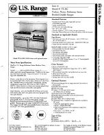
GRIDDLE SPECIFICATIONS

NOMINAL AMPS PER LINE

WEIGHT

THREE PHASE

440 VOLT

MODEL

NUMBER

TOTAL

kW

LINE 1

LINE 2

LINE 3

CLG-36PB-S

18.0

21.7

21.7

21.7

405 lbs.

Summary of Contents for CLGPB-36-S

Page 1: ...00 Merrill Creek Parkway Everett WA 98203 Phone 425 349 2400 Fax 425 349 2733 WWW LANGWORLD COM Copyright 2002 Installation Operation Maintenance Troubleshooting Model CLGPB 36 S Electric Cruise Line...

Page 2: ...INTENANCE CAN CAUSE PROPERTY DAMAGE INJURY OR DEATH READ THE INSTALLATION OPERATING AND MAINTENANCE INSTRUCTIONS THOROUGHLY BEFORE INSTALLING OR SERVICING THIS EQUIPMENT DANGER POTENTIALLY HAZARDOUS S...

Page 3: ...HAPTER PAGE 1 TABLE OF CONTENTS 3 2 READ FIRST 4 3 UNPACKING 5 4 INSTALLATION 6 5 INITIAL START UP 7 6 OPERATION 8 7 CLEANING 9 8 TROUBLESHOOTING 10 9 PARTS LIST 11 10 EXPLODED VIEWS 12 11 WIRING DIAG...

Page 4: ...h as a vent hood grease extractors fire extinguisher systems must conform to their applicable National State and locally recognized installation standards CAUTION ALWAYS KEEP THE AREA NEAR THE APPLIAN...

Page 5: ...ar its intended location as practical The crating will help protect the unit from the physical damage normally associated with moving it through hallways and doorways 3 3 Un crating The griddle will a...

Page 6: ...the installation NOTICE The installation of any components such as a vent hood grease extractors fire extinguisher systems must conform to their applicable National State and locally recognized instal...

Page 7: ...SURFACE 5 2 Season the Grill The cooking surface must be seasoned in order to reduce product sticking To season heat the griddle to 250 degrees Once at 250 degrees coat the cooking surface with a non...

Page 8: ...ch cooking section If product is loaded directly over the temperature sensor that section will turn on and the element will heat the entire cooking section If the product is loaded to the side front o...

Page 9: ...each meal Keep the griddle surface clean After each cooking load scrape the griddle surface with the grooved griddle cleaning tool to remove any carbonized grease The griddle surface should be cleane...

Page 10: ...service station directory or call the factory at 1 800 224 LANG 5264 or WWW LANGWORLD COM for the service station nearest you WARNING BOTH HIGH AND LOW VOLTAGES ARE PRESENT INSIDE THIS APPLIANCE WHEN...

Page 11: ...01 28 8 Griddle Stand Assembly LGCL 710 3 9 Screw 10 32 X 5 S S Hex Head Cap 20111 09 10 Element 440 Volt 5991 Watts 11030 48 11 Nut 10 32 Hex Head 20303 02 12 Element Pan Zig Zag LGCL 439 13 Element...

Page 12: ......

Page 13: ...13 EXPLODED VIEW CONT D...

Page 14: ...14 EXPLODED VIEW CONT D...

Page 15: ...15 WIRING DIAGRAM...

Page 16: ...16 THIS PAGE IS INTENTIONALLY LEFT BLANK...

Page 17: ...ing the warranty period As to warranty service in the territory described above Lang will absorb labor and portal to portal transportation costs time mileage for the first 12 twelve months from the da...

Reviews: