


E1/G.703 F
IBER
O
PTIC
M
ODEM
O
PERATING
M
ANUAL
IOA76-1F
5
May 2009
2 C
ONNECTORS AND INDICATORS
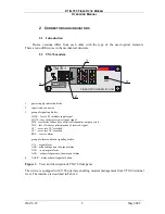
2.1 Introduction
Device versions differ from each other with the type of the used optical elements.
There are no differences in the mechanical structure.
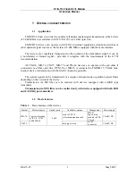
2.2 TM-76 modem
6-Tx
5-Rx
4-SG
FIBER OPTIC MODEM E1/G.703
AACK
TM-76.1
RS-232
LO
E
S
LO
O
S
10
10
-6
-3
RA
L
AC
K
AC
K
LD
F
LO
F
UA
NUA
1
2
3
4
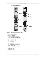
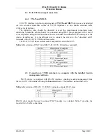
1 -
power supply indication diode
2 -
supervision connector
3 -
group of signaling diodes:
LOES – loss of E1 interface input signal
LOOS – loss of optical receiver input signal
LDF– laser diode failure (loss of optical transmitter output power)
LOF – loss of frame synchronization of received signal
10
-3
– error rate 10
-3
exceeded
10
-6
– error rate 10
-6
exceeded
RAL – remote alarm
group of alarm condition signaling diodes:
UA – urgent alarm
ACK – acknowledgement of urgent alarm
NUA – non-urgent alarm
ACK – acknowledgement of non-urgent alarm
4-
AACK – alarm acknowledgment button
Figure 3.
View and description of TM-76 front panel
The device is equipped with V.28 interface enabling modem management from VT100 terminal
level. The interface is described in Table 2.
Summary of Contents for MD-76
Page 42: ...E1 G 703 FIBER OPTIC MODEM OPERATING MANUAL IOA76 1F 36 May 2009 Figure 27 G 826 statistics...
Page 54: ......
Page 55: ......


