4-6
F-459-R1
ELECTRICAL SYSTEM
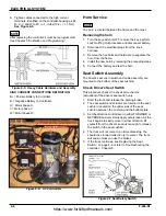
8. Tighten cables connected to the high current
terminals, identified on the controller housing as B+,
B-, U, V and W to 85 +/- 1- in-lbs(10.2 +/- 1.1 Nm).
See Figure 4-5.
NOTE
After replacing the controller it must be reprogrammed.
See Chapter 5 “Calibration and Programming”.
Figure 4-5: Heavy Cable Hardware and Assembly
HIGH CURRENT CONNECTIONS DEFFINITION:
B+ = Positive Battery to Controller.
B- = Negative Battery to Controller.
U = Motor phase U.
V = Motor phase V.
W = Motor phase W.
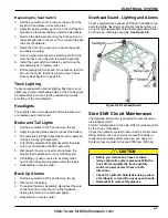
Figure 4-6: AC Controllers
Horn Service
NOTE
The horn is located between the frame and the mast.
Removing the horn
1. Turn the key switch is OFF, remove the key, perform
Lock Out/Tag Out procedure and disconnect battery.
2.
Disconnect the electrical plugs from the truck
harness.
3.
Remove the hex bolts and hardware to separate the
horn from the frame.
4.
Install the new horn by reversing the preceding steps.
5.
Connect the battery and test the horn.
Seat Switch Assembly
The driver's seat micro switch and cable assembly are
mounted to the bottom of the seat cushion.
Check Driver’s Seat Switch
This procedure checks the physical mechanics
(actuation) of the driver’s seat switch only.
1.
Start the truck and release the parking brake.
2. The seat switch and actuator are internal to the seat
cushion, located on the under side of the seat
cushion between the cushion and the bottom plate.
3.
Set the direction control lever in either FORWARD or
REVERSE and very slowly apply acceleration. As the
truck begins to slowly move in either direction, lift
yourself from the driver’s seat just enough to release
the switch in the seat cushion.
4. The truck will not come to an immediate stop. You
should lose forward direction (or reverse). The truck
will coast unless you use the brakes.
5.
If the truck continues, see Replacing the Seat
Switch,” on page 4-6 or refer to Troubleshooting the
controller - Chapter 5.
Figure 4-7 Seat Safety Switch
https://www.forkliftpdfmanuals.com/

