9K998-2306
2-25
Console w/Clutch Control -
Seed Shaft Sensor - Optional
Seed Shaft Sensor and Magnet Wheel Assembly
Installation
1. Remove the two #10-24 x 3/4 Self Tapping Screws
from the Magnet Wheel Assembly.
2. Position half of the Magnet Wheel Assembly on the
Seed Shaft. Ensure it fits squarely onto Seed Shaft.
3. Mount the other half, ensuring it fits squarely onto
Seed Shaft.
4. Fasten the two halves together using two #10-24 x 3/4
Self Tapping Screws.
Do not over tighten
.
5. Identify the Seed Meters on either side of the Magnet
Wheel Assembly and remove the 1/4-20 hardware.
6. Insert Seed Shaft Sensor into Shaft Sensor Bracket
Slot.
7. Align the Shaft Sensor Bracket with the two 1/4-20
Bolts. Secure with existing Lock Washers and Nuts.
8. Position Seed Shaft Sensor so it is 1/8" from the
both Seed Shaft Sensor Retaining Nuts.
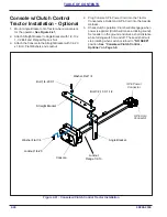
Figure 2-39: Console w/Clutch Control Detail
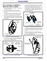
Figure 2-40: Console w/Clutch Control Seed Shaft Sensor
Retaining Nuts
1/8" Max
Magnet Wheel
Assembly
Shaft Sensor
Bracket
Seed Shaft
Sensor
Magnet
Screw,
Self Tapping
#10-24 x 3/4
Seed Shaft
Magnet Wheel
Assembly
11/16 Hex Shaft
Machine Screw,
1/4-20 x 3/4
Existing
Lock Washer,1/4-20
Existing
Nut,1/4-20
Shaft Sensor
Bracket
Seed Shaft
Sensor
Seed Shaft
Machine Screw,
1/4-20 x 3/4
Screw,
Self Tapping
#10-24 x 3/4
Shaft Sensor Bracket
Seed Shaft
Sensor
Magnet Wheel
Assembly
11/16 Hex Shaft
Existing
Lock Washer,1/4-20
Existing
Nut,1/4-20
Summary of Contents for Brillion Turfmaker II Series
Page 4: ......
Page 18: ...1 10 9K998 2306 TABLE OF CONTENTS Table provided for general use NOTES...
Page 45: ...9K998 2306 2 27 TABLE OF CONTENTS Table provided for general use NOTES...
Page 53: ...9K998 2306 2 35 TABLE OF CONTENTS Table provided for general use NOTES...
Page 61: ...9K998 2306 2 43 TABLE OF CONTENTS Table provided for general use NOTES...
Page 94: ...4 8 9K998 2306 TABLE OF CONTENTS Table provided for general use NOTES...


