


h.
Clean the mounting surfaces with a good
grade commercial cleaner and soft rag. Dry
all component parts with a clean, absorbent
cloth or paper. Lubricant will not adhere to
surfaces wet with solvent.
i.
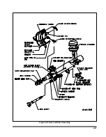
Place the drum over the hub and brake
shoes being careful not to damage the
threads on the studs
(See Figure 4-15)
. Make
sure the drum seats flat against the hub
flange and mates properly with the hub pilot.
There should be no interference between the
brake drum pilot chamfer and the corner ra-
dius on the hub. If interference exists, the hub
will not be able to function properly.
j.
Install inner bearing, cone, and seal.
IMPORTANT
DO NOT MIX NEW CUPS WITH OLD CONES
OR NEW CONES WITH OLD CUPS.
k.
If studs are marked “R” or “L”, right hand (R)
hubs should be installed on the curbside of
the vehicle, left hand (L) hubs should be in-
stalled on the driver side.
WARNING
FAILURE TO USE THE CORRECT
STUD ON THE CORRECT SIDE MAY
CAUSE LOOSENING OF THE HUB
STUDS DURING OPERATION, RE-
SULTING IN LOSS OF A WHEEL.
l.
Place the hub or wheel over the axle spindle
being careful to align the hub bore with the
axle. Do not damage the seal. Support the
hub assembly until the outer bearing cone
and spindle nut are installed, to avoid damag-
ing the seal.
m.
Install the outer bearing cone and inner
spindle nut, tightening the nut until it is snug
against the outer bearing cone. Remove the
hub support allowing the hub to rest on the
bearings.
n.
Install and adjust bearings
(See Section
4-10, Wheel Bearing Lubrication and Ad-
justment).
o.
Install the hub cap with the proper gasket.
Tighten the cap screws of the hub cap to 15
to 20 ft-lbs. of torque.
p.
Remove the filler plug and fill the hub cavity
to the recommended level with a gear type
oil.
4-26
Figure 4-15 Outboard Mount Hub and Drum
Summary of Contents for 600B Series
Page 8: ......
Page 12: ......
Page 14: ...3 2 Figure 3 1 Front Trailer Terminology Figure 3 2 Rear Trailer Terminology...
Page 18: ...3 6 Figure 3 4 Hydraulic Controls...
Page 26: ...3 14 Figure 3 7 Steps for Loading and Unloading...
Page 32: ...3 20 Figure 3 10 Dock Leveler Operation...
Page 38: ...3 26 Figure 3 14 Rear Impact Guard and Antilock Brake System...
Page 42: ...4 2 Figure 4 1 Lubrication Points...
Page 48: ...4 8 Figure 4 3 600B Wiring Diagram...
Page 49: ...4 9 Figure 4 4 Remote Wiring Diagram...
Page 52: ...4 12 Figure 4 5 Tandem Axle Air Ride Suspension System Figure 4 6 Air Ride Height Adjustment...
Page 54: ...4 14 Figure 4 7 Triple Axle Air Ride Suspension System...
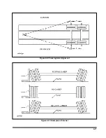
Page 57: ...4 17 Figure 4 9 Checking Axle Alignment Figure 4 10 Examples of Camber...
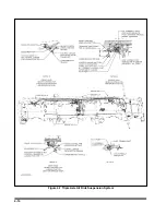
Page 61: ...4 21 Figure 4 13 Axle and Brake Assembly...
Page 71: ...4 31 Figure 4 21 Dock Leveler Leg Assembly...
Page 73: ...4 33 Figure 4 22 Crank Landing Gear Assembly...
Page 84: ...NOTES 5 10...


