


4-8.3
Emergency Relay Valve Maintenance
Every 3600 operating hours, 100,000 miles, or
yearly, the Emergency Relay Valve should be dis-
assembled, cleaned, and lubricated by a trained
technician.
WARNING
REPAIR OR REPLACEMENT OF THE
RELAY/EMERGENCY VALVE IS A COM-
PLEX OPERATION AND SHOULD BE
PERFORMED BY TRAINED SERVICE
PERSONNEL. CONTACT A LANDOLL
AUTHORIZED SERVICE CENTER OR
THE LANDOLL FACTORY FOR SERVIC-
ING.
4-8.4
Brake Assembly Maintenance
The brake assemblies should be inspected and
adjusted every 2,000 miles or monthly. Examine
the brake linings visually to locate the lining show-
ing the greatest amount of wear. The wheel and
drum should be removed and the linings replaced
if the thinnest portion of the lining is 3/8 in. (9.5
mm) or less. Do not allow the linings to wear thin
enough that the lining rivet contacts the drum.
(See
Figure 4-12)
. Lubricate brake assembly per
Figure
4-1, Lubrication Points
and
Table 4-2, Mainte-
nance Schedule.
WARNING
DO NOT ALLOW GREASE TO CON-
TACT BRAKE LININGS AS THIS
COULD RESULT IN REDUCED BRAK-
ING PERFORMANCE.
a. Brake Adjustment
This semitrailer is equipped with automatic
slack adjusters which compensate for brake lining
wear and keep brakes adjusted. Brakes should not
be adjusted manually except when relining brakes.
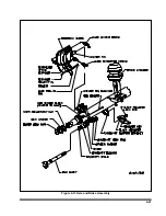
b. Disassembly for 12-1/4" X 7-1/2" Brakes
(See Figure 4-13)
1.
Release brakes and back off slack
adjuster.
2.
Remove slack adjuster lock ring and slack
adjuster.
3.
Remove drum assembly
(See Figure
4.
Remove anchor pin retainers, washers,
and bushings.
5.
Remove anchor pins and brake shoes.
6.
Remove brake return springs.
7.
Remove camshaft lock ring, spacer washer
and camshaft
8.
Remove roller pin retainers.
9.
Remove roller pins and rollers from shoes.
10.
Remove camshaft bushings and seals from
spider.
11.
After removing the shoes, completely
inspect all brake components, servicing
as necessary.
4-20
Figure 4-12 Brake Lining Wear
Summary of Contents for 600B Series
Page 8: ......
Page 12: ......
Page 14: ...3 2 Figure 3 1 Front Trailer Terminology Figure 3 2 Rear Trailer Terminology...
Page 18: ...3 6 Figure 3 4 Hydraulic Controls...
Page 26: ...3 14 Figure 3 7 Steps for Loading and Unloading...
Page 32: ...3 20 Figure 3 10 Dock Leveler Operation...
Page 38: ...3 26 Figure 3 14 Rear Impact Guard and Antilock Brake System...
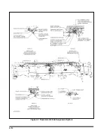
Page 42: ...4 2 Figure 4 1 Lubrication Points...
Page 48: ...4 8 Figure 4 3 600B Wiring Diagram...
Page 49: ...4 9 Figure 4 4 Remote Wiring Diagram...
Page 52: ...4 12 Figure 4 5 Tandem Axle Air Ride Suspension System Figure 4 6 Air Ride Height Adjustment...
Page 54: ...4 14 Figure 4 7 Triple Axle Air Ride Suspension System...
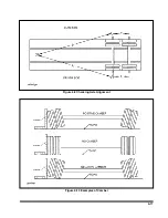
Page 57: ...4 17 Figure 4 9 Checking Axle Alignment Figure 4 10 Examples of Camber...
Page 61: ...4 21 Figure 4 13 Axle and Brake Assembly...
Page 71: ...4 31 Figure 4 21 Dock Leveler Leg Assembly...
Page 73: ...4 33 Figure 4 22 Crank Landing Gear Assembly...
Page 84: ...NOTES 5 10...


