


e.
Replace any missing or illegible decals. Re-
place any missing or damaged reflective tape.
f.
Use Troubleshooting Guide to check for
“SYMPTOMS” AND “PROBLEMS” of any
semitrailer system not functioning correctly, or
where wear, distortion, or breakage can be
found. Administer “REMEDY” according to
right-hand column of Troubleshooting guide.
g.
After disassembling any components, thor-
oughly clean dirt and old lubricant from all
parts. Do not use a wire brush on any bearing
parts or surfaces — use a stiff bristle brush.
Do not use compressed air, or spin bearing
parts when cleaning. These practices can
throw solvents, dirt, or metal particles into
your eyes. Dry clean parts with lint free,
clean, soft, absorbent, cloth or paper. Wash
and dry hands.
h.
Inspect seals, seal wiping surfaces, bearing
caps, and bearing cones for wear, pitting,
chipping, or other damage.
4-3 GOOSENECK, FRAME, AND DECK
4-3.1
Repairing Structural Defects
If any structural defect is found, the fault must
be corrected before further use of the vehicle. To
continue usage could endanger the trailer, its load,
personnel, traffic, and properties. If any cracks or
breaks are found, contact the Landoll factory for
repairs. Inspect the deck daily for broken or miss-
ing planks or missing attachments. Replace any
defective parts promptly.
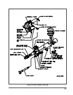
4-3.2
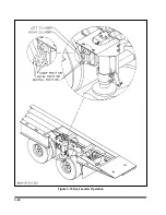
Fifth Wheel Latch Adjustment
a.
To adjust fifth wheel latch assembly, sup-
port fifth wheel plate and adjust rear nut until
the cam just touches the flat surface on the
latch
(See Figure 4-2).
b.
Then tighten the front nut compressing the
spring to approximately 10-3/8" or until there
is sufficient tension to hold the fifth wheel
plate in place.
4-6
Figure 4-2 Fifth Wheel Latch Adjustment
Summary of Contents for 600B Series
Page 8: ......
Page 12: ......
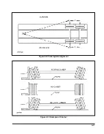
Page 14: ...3 2 Figure 3 1 Front Trailer Terminology Figure 3 2 Rear Trailer Terminology...
Page 18: ...3 6 Figure 3 4 Hydraulic Controls...
Page 26: ...3 14 Figure 3 7 Steps for Loading and Unloading...
Page 32: ...3 20 Figure 3 10 Dock Leveler Operation...
Page 38: ...3 26 Figure 3 14 Rear Impact Guard and Antilock Brake System...
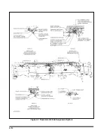
Page 42: ...4 2 Figure 4 1 Lubrication Points...
Page 48: ...4 8 Figure 4 3 600B Wiring Diagram...
Page 49: ...4 9 Figure 4 4 Remote Wiring Diagram...
Page 52: ...4 12 Figure 4 5 Tandem Axle Air Ride Suspension System Figure 4 6 Air Ride Height Adjustment...
Page 54: ...4 14 Figure 4 7 Triple Axle Air Ride Suspension System...
Page 57: ...4 17 Figure 4 9 Checking Axle Alignment Figure 4 10 Examples of Camber...
Page 61: ...4 21 Figure 4 13 Axle and Brake Assembly...
Page 71: ...4 31 Figure 4 21 Dock Leveler Leg Assembly...
Page 73: ...4 33 Figure 4 22 Crank Landing Gear Assembly...
Page 84: ...NOTES 5 10...


