


3-12 PULL OUT EXTENSIONS
DANGER
1. DO NOT OPERATE IF ANY EXTEN-
SION IS NOT LOCKED IN PLACE BY
SPRING LOADED LOCKING PIN. IN-
SPECT ALL EXTENSIONS TO INSURE
EACH IS LOCKED SECURELY IN POSI-
TION BY THE SPRING LOADED LOCK-
ING PIN.
2. REMOVE AND SECURELY STORE
ALL WHEEL COVER EXTENSIONS
WHICH ARE NOT HELD DOWN SE-
CURELY BY THE LOAD WHEN TRANS-
PORTING TRAILER.
CAUTION
DO NOT PULL EXTENSIONS OUT OF
TRAILER FRAME WITHOUT ADE-
QUATE SUPPORT. FAILURE DO SO
MAY CAUSE INJURY.
3-12.1
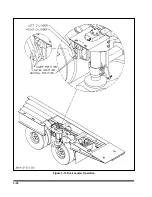
Pull out extensions are adjustable in six
inch increments. Extension lock pin can be
held in released position when pulled back
and rotated one quarter turn into catch
(See
Figure 3-6)
.
3-12.2
Adjust pullout to desired extended posi-
tion and trip lock pin to secure.
WARNING
1. DO NOT OVERLOAD EXTENSIONS.
OVERWIDTH RATINGS ARE GIVEN IN
STANDARD SPECIFICATIONS.
2. DO NOT SECURE LOAD TO OVER-
WIDTHS OR UNDERCARRIAGE. SE-
CURE LOAD FRAME TO MOUNTED D-
RINGS OR GOTCHAS LOCATED IN
THE APPROACH PLATE AND FRAME
BEAM FLANGES. FAILURE TO DO SO
MAY CAUSE SERIOUS INJURY OR
DEATH.
3-12.3
Additional blocking or planking may be
needed to support load wheels/tracks be-
tween the rearmost overwidth and the
ground.
3-12.4
Install the flag holders in the second
hole of the front, center, and rear overwidth
tubes and secure with lock washer and wing
nut so the flag mounting tube is pointing up-
ward. Secure approved flags in the mounting
tube with the spring loaded retaining pin.
Reference FMCSR Part 393.87 and applica-
ble state and local regulations concerning
flags on projecting loads.
3-12.5
If required, display oversize load signs.
3-11
Figure 3-6 Pull Out Extensions
Summary of Contents for 600B Series
Page 8: ......
Page 12: ......
Page 14: ...3 2 Figure 3 1 Front Trailer Terminology Figure 3 2 Rear Trailer Terminology...
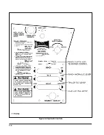
Page 18: ...3 6 Figure 3 4 Hydraulic Controls...
Page 26: ...3 14 Figure 3 7 Steps for Loading and Unloading...
Page 32: ...3 20 Figure 3 10 Dock Leveler Operation...
Page 38: ...3 26 Figure 3 14 Rear Impact Guard and Antilock Brake System...
Page 42: ...4 2 Figure 4 1 Lubrication Points...
Page 48: ...4 8 Figure 4 3 600B Wiring Diagram...
Page 49: ...4 9 Figure 4 4 Remote Wiring Diagram...
Page 52: ...4 12 Figure 4 5 Tandem Axle Air Ride Suspension System Figure 4 6 Air Ride Height Adjustment...
Page 54: ...4 14 Figure 4 7 Triple Axle Air Ride Suspension System...
Page 57: ...4 17 Figure 4 9 Checking Axle Alignment Figure 4 10 Examples of Camber...
Page 61: ...4 21 Figure 4 13 Axle and Brake Assembly...
Page 71: ...4 31 Figure 4 21 Dock Leveler Leg Assembly...
Page 73: ...4 33 Figure 4 22 Crank Landing Gear Assembly...
Page 84: ...NOTES 5 10...


