


3-3 COUPLING OF THE TRACTOR TO THE SEMITRAILER
DANGER
KEEP ALL PERSONNEL CLEAR OF
FRONT, REAR, AND SIDES OF TOW-
ING VEHICLE AND SEMITRAILER DUR-
ING COUPLING, COMPONENT OPERA-
TIONS, AND UNCOUPLING. FAILURE
TO STAY CLEAR CAN RESULT IN SE-
RIOUS PERSONAL INJURY OR DEATH.
3-3.1
Verify the semitrailer wheels are
chocked and brakes function properly.
3-3.2
Make certain the coupler of the towing
vehicle’s fifth wheel is open by pulling the
latch handle.
3-3.3
Slowly back the towing vehicle so its
fifth wheel contacts the front of the king pin
plate on the semitrailer and slips under it.
Continue backing until the fifth wheel coupler
locks onto the semitrailer kingpin.
CAUTION
PUSHING THE SEMITRAILER BACK-
WARDS CAN DAMAGE PARKING
STANDS.
3-3.4
Verify the vehicle coupling is secure by
attempting to pull the tractor forward a few
inches. If the tractor disconnects from the
semitrailer, locate source of coupling failure;
repair before continuing; and repeat
Section
3-3.5
Check that the towing vehicle couples
securely to the semitrailer before setting tow-
ing vehicle and semitrailer parking brakes.
IMPORTANT
KEEP BRAKES ENGAGED FOR REMAINDER
OF HOOKUP, CHECKOUT PROCEDURES AND
PARK
3-4 CONNECTING TRACTOR SERVICES TO THE SEMITRAILER
3-4.1
Connect the towing vehicle 7-pole elec-
trical plug to the electrical receptacle on the
front of the semitrailer
(See Figure 3-3).
IMPORTANT
THE KEY ON THE PLUG AND THE KEYWAY IN
THE SOCKET MUST BE PROPERLY ALIGNED
BEFORE INSERTING THE PLUG INTO THE
SEMITRAILER SOCKET.
CAUTION
HYDRAULIC OPERATING PRESSURES
GREATER THAN 2500 PSI CAN CAUSE
DAMAGE TO THE TRAILER.
3-4.2
If you have not already done so, con-
nect the tractor hydraulic lines to the semi-
trailer unless your semitrailer is equipped
with the self-contained hydraulic power en-
gine package.
IMPORTANT
SOME OIL MAY NEED TO BE REMOVED FROM
THE TRACTOR RESERVOIR TO ALLOW ROOM
FOR 12 GALLONS OF ADDITIONAL OIL DIS-
PLACED FORM THE TRAILER HYDRAULIC
SYSTEM.
3-4.3
Air Lines:
See Section 3-2.
3-4
Summary of Contents for 600B Series
Page 8: ......
Page 12: ......
Page 14: ...3 2 Figure 3 1 Front Trailer Terminology Figure 3 2 Rear Trailer Terminology...
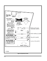
Page 18: ...3 6 Figure 3 4 Hydraulic Controls...
Page 26: ...3 14 Figure 3 7 Steps for Loading and Unloading...
Page 32: ...3 20 Figure 3 10 Dock Leveler Operation...
Page 38: ...3 26 Figure 3 14 Rear Impact Guard and Antilock Brake System...
Page 42: ...4 2 Figure 4 1 Lubrication Points...
Page 48: ...4 8 Figure 4 3 600B Wiring Diagram...
Page 49: ...4 9 Figure 4 4 Remote Wiring Diagram...
Page 52: ...4 12 Figure 4 5 Tandem Axle Air Ride Suspension System Figure 4 6 Air Ride Height Adjustment...
Page 54: ...4 14 Figure 4 7 Triple Axle Air Ride Suspension System...
Page 57: ...4 17 Figure 4 9 Checking Axle Alignment Figure 4 10 Examples of Camber...
Page 61: ...4 21 Figure 4 13 Axle and Brake Assembly...
Page 71: ...4 31 Figure 4 21 Dock Leveler Leg Assembly...
Page 73: ...4 33 Figure 4 22 Crank Landing Gear Assembly...
Page 84: ...NOTES 5 10...


