


2-28
F-982-0223
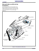
ASSEMBLY
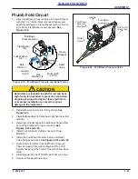
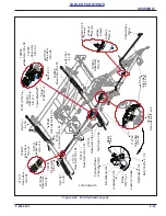
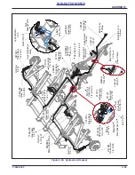
Plumb Lift Circuit
1. Attach the Counter Balance Valve to the inside frame
bracket with 5/16-18 x Bolt, Flat Washer, Lock
Washer and Nut,
2. Install Counter Balance Valve fittings.
Figure 2-24: Counter Balance Valve
3. Attach Hoses to Counter Balance Valve. Route the
Hoses to the right side of the Drawbar and clamp
each set of system’s hoses with hose clamps. Secure
with Flat Washer under the head of 3/8-16 x 5 Bolt
and Locknut. Continue routing the hoses to the front
of the Drawbar up the Hose Holder Bracket. If not
already done, install 3/8-16 x 5 Bolt onto Hose Holder
Bracket with Hex Nut. Place the Hose Holder Clamp
over the bolt and hoses. Secure with Hose Holder
Wing Nut.
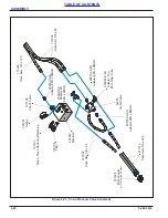
4. Install the Lift Cylinders and Hitch Leveler 4 x 8
Cylinder fittings.
CAUTION
5. Install Restrictor and Branch Tee into the base end
and O-Ring Branch Tee into the rod end of the 4 x 16
cylinder.
6. Install Lift Cylinder and Hitch Leveler Hoses.
7. Secure all hoses with Cable Ties and Tie Wraps.
Wrap the Lift Circuit System hoses near the Tractor
Tips with Blue Hose Wrap.
8. Install Wings if not already assembled.
Frame Installation” on page 2-50.
9. Assemble Lifts on Wings.
10. Install 4 x 14 Cylinders on Wing Lifts.
11. Install Wing Rests and Bearing Hangers if not
assembled.
See “Bearing Hanger and Wing Rest
12. Assembly Wing Lift Cylinder Hoses.
Frame
Bracket
Counter Balance
Valve
Bolt,5/16-18 x 2
Flat Washer,5/16
Lock Washer,5/16
Nut,5/16-18
A Restrictor is used in the base end of the Hitch
Leveling 4 x 16 Cylinder. Removal of this restrictor
can cause uncontrolled movement of the front of
the machine. Improper installation can result in
serious damage to the implement.
Summary of Contents for 3631-30
Page 4: ......
Page 8: ...iv F 982 0223 TABLE OF CONTENTS ...
Page 33: ...ASSEMBLY F 982 0223 2 15 TABLE OF CONTENTS Table provided for general use NOTES ...
Page 36: ...2 18 F 982 0223 ASSEMBLY TABLE OF CONTENTS Table provided for general use NOTES ...
Page 45: ...ASSEMBLY F 982 0223 2 27 TABLE OF CONTENTS Table provided for general use NOTES ...
Page 50: ...2 32 F 982 0223 ASSEMBLY TABLE OF CONTENTS Table provided for general use NOTES ...
Page 57: ...ASSEMBLY F 982 0223 2 39 TABLE OF CONTENTS Table provided for general use NOTES ...
Page 63: ...ASSEMBLY F 982 0223 2 45 TABLE OF CONTENTS Table provided for general use NOTES ...
Page 72: ...2 54 F 982 0223 ASSEMBLY TABLE OF CONTENTS Table provided for general use NOTES ...
Page 82: ...2 64 F 982 0223 ASSEMBLY TABLE OF CONTENTS Table provided for general use NOTES ...
Page 89: ...ASSEMBLY F 982 0223 2 71 TABLE OF CONTENTS Figure 2 62 Right Hand Wing Harrow ...
Page 93: ...ASSEMBLY F 982 0223 2 75 TABLE OF CONTENTS Table provided for general use NOTES ...
Page 102: ...2 84 F 982 0223 ASSEMBLY TABLE OF CONTENTS Table provided for general use NOTES ...
Page 114: ...2 96 F 982 0223 ASSEMBLY TABLE OF CONTENTS Table provided for general use NOTES ...
Page 138: ...4 10 F 982 0223 MAINTENANCE TABLE OF CONTENTS Table provided for general use NOTES ...
Page 142: ...5 4 F 982 0223 SPECIFICATIONS TABLE OF CONTENTS Table provided for general use NOTES ...


