Landis McKay Stitcher 77 Operator Instructions Manual Download Page 18

-16-

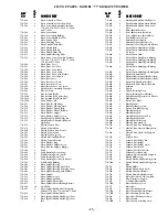
LIST OF PARTS - MODEL “77” MCKAY STITCHER

CHAMPION AND LANDIS COMBINATION HAND CHANNELER AND GROOVER

REQ’DREQ’DREQ’DREQ’DREQ’D

P

P

P

P

PAR

AR

AR

AR

ART

T

T

T

T

NO.

NO.

NO.

NO.

NO.

NAME OF P

NAME OF P

NAME OF P

NAME OF P

NAME OF PAR

AR

AR

AR

ART

T

T

T

T

HC50

Right Hand Channeler & Groover
Complete with Sharpening Stone

HC50A

Left Hand Channeler & Groover
Complete with Sharpening Stone

PARTS

HC53

1

Hand Channeler Frame

HC54

1

Hand Groover Frame

HC58

1

Hand Channeler Knife

HC62

1

Semi-English Knife

HC63

1

Groover Knife

HC67

2

Edge Gauge

HC68

4

Edge Gauge Screw

HC69

3

Edge Gauge Washer

HC73

1

Hand Channeler Handle

HC77

1

Sharpening Stone

P

P

P

P

PAR

AR

AR

AR

ART

T

T

T

T

NO.

NO.

NO.

NO.

NO.

NAME OF P

NAME OF P

NAME OF P

NAME OF P

NAME OF PAR

AR

AR

AR

ART

T

T

T

T

MX-1R

McKay Lip Channeler - Right
Hand Complete

MX-1L

McKay Lip Channeler - Left
Hand Complete

X-6R

McKay Lip Channeler Knife - Right
Hand

X-6L

McKay Lip Channeler Knife - Left
Hand

LANDIS HAND GROOVERS

X-5R

McKay Groover - Right Hand
Complete

X-5L

McKay Groover - Left Hand
Complete

X-4R

McKay Groover Knife - Right Hand

X-4L

McKay Groover Knife - Left Hand

REQ’DREQ’DREQ’DREQ’DREQ’D

P

P

P

P

PAR

AR

AR

AR

ART

T

T

T

T

NO.

NO.

NO.

NO.

NO.

NAME OF P

NAME OF P

NAME OF P

NAME OF P

NAME OF PAR

AR

AR

AR

ART

T

T

T

T

REQ’DREQ’DREQ’DREQ’DREQ’D

P

P

P

P

PAR

AR

AR

AR

ART

T

T

T

T

NO.

NO.

NO.

NO.

NO.

NAME OF P

NAME OF P

NAME OF P

NAME OF P

NAME OF PAR

AR

AR

AR

ART

T

T

T

T

77-S-796

1

Motor Switch Rod

77-S-850

1

1/4” Hollow Hex Wrench

77-S-852

1

3”  Screw Driver

77-S-855

1

1/4” Square Socket Wrench

77-S-856

1

3/16” Hollow Hex “L” Wrench

77-S-861

1

Oil Can

77-S-863

1

Threading Wire - Straight

77-S-864

1

Threading Wire - Bent

77-S-865

1

Can  Liquid Wax

77-S-870

1

Model Name Plate

77-S-871

2

Model Name Plate Drive
Screw

ILLUSTRATION OF CHAMPION COMBINATION HAND CHANNELER AND GROOVER

Champion Combination

Hand Channeler and

Groover

Has an Adjustable Gauge.  Groove can be
cut in channel where desired.

Quickly adjusted for cut-
ting channel any margin
from the edge of sole or
to make thin or thick lip.

Summary of Contents for McKay Stitcher 77

Page 1: ...Shoe Systems Plus Inc 249 W Main Street Goshen NY 10924 1 800 354 6278 INSTRUCTIONS TO OPERATORS LANDIS CHAINSTITCH McKAY STITCHER Model 77 CATALOGUE OF PARTS ...

Page 2: ......

Page 3: ...ifles arise at times which can be eliminated by consulting the following instructions which will enable you to care for your machine properly and keep it in perfect adjustment For your particular benefit it is desired that you familiarize yourself as much as possible with the operation of the machine The following instructions will be of considerable assistance towards helping you in maintaining a...

Page 4: ...e complete part number of the part needed and quantity 2 Give the Model and Serial Number of your machine 3 Write your name and address as plainly as possible 4 Prices of parts do not include postage or insurance This is extra Parts are usually shipped parcel post insured 5 Prices are subject to change without notice NOTE When mailing parts to Factory be sure to write your name and address plainly...

Page 5: ...hrough Lower Wax Pot Roll then up through Wax Pot Stripper through Thread Guide Pin and under Horn Thread Roll and up Horn to small hole in Whirl A small curved Thread Hook will be found in the supply package See Figure No 1 LIQUID WAX CLEANING WAX POT Stir Liquid Wax thoroughly before putting it in Wax Pot Use thinner to thin wax when too thick or heavy Order Landis Yellow Label Machine Cleaner W...

Page 6: ...re No 3 NEEDLE BAR FRICTION For more friction turn Adjusting Screw in top of Main Head to the right for less friction turn screw left This Friction Screw is adjusted at the factory and requires little attention It is used to hold Needle Bar in place when Latch is released A few drops of oil should be placed in Oil Hole each day CAST OFF FRICTION The Cast Off Friction is adjusted at the factory so ...

Page 7: ...dle remove the Needle spring the Cast Off in as much as nec essary TO REMOVE AND REPLACE CAST OFF Loosen Cast Off Set Screw S 97 Loosen and take off Needle Clamp Collar S 93 remove Cast Off To replace Cast Off insert Cast Off in Cast Off Block tighten Set Screw and replace Needle Clamp Collar See figure No 4 ADJUSTMENTS FOR ELIMINATING THE SKIPPING OF STITCHES See that the following are in proper ...

Page 8: ... to stitch along the old line of stitching if the make up of the shoe enables the line of stitching to catch the upper In stitching the Turn shoe it is desirable to stitch outside of the inside channel of the turn shoe in order to catch the upper In stitching the Welt shoe it is desirable to stitch as close to the edge of the inner sole as the Horn will permit The same applies to the stitching of ...

Page 9: ...ring but a second or two and when properly done it permits of practically closing the grooved channel over the thread See figure No 7 The Aloft Presser Foot should be inserted when stitching aloft This Presser Foot can be used for any other type of channel work You will find aloft stitching extremely simple THREAD It is highly important that a good grade of right twist thread be used and should yo...

Page 10: ...n to see that the Whirl S 507 is cor rectly timed Two settings of the machine are neces sary 1st Revolve the machine by hand until the ar row on the Feed Cam S 255 coincides with the Arrow on the Main Head See figure No 5 2nd Set the Horn at the left until the marks on the Horn and Horn Table coincide See figure No 11 With these settings arranged insert the Whirl so that the small hole in Whirl co...

Page 11: ... is lined up at the factory Should the occasion arise at any time for re alignment it can be accomplished by the following procedure Loosen four Screws S 531 under Horn Table slightly which will permit tapping the Horn to correct alignment Tap into a central position so that hole in Horn Cap runs true After firmly tighten ing Horn Holding Screws you can check the position by putting needle down in...

Page 12: ... S 40 S 41 S 48 S 36 S 37 S 42 S 62 S 64 S 65 S 61 S 60 S 70 S 71 S 128 S 150 S 63 S 38 S 77 S 117 S 172 S 152 S 151 S 166 S 140 S 139 S 136 S 137 S 160 S 170 S 171 S 39 S 76 S 75 S 85 S 84 S 104 S 105 S 82 S 81 S 86 S 93 S 94 S 97 S 99 S 109 S 96 S 116 S 97 S 198 S 199 S 186 S 130 S 131 S 188 S 141 S 205 S 206 S 192 S 191 S 190 S 205 S 202 S 196 S 197 S 95 S 98 ...

Page 13: ...366 S 347 S 346 S 347 S 342 S 343 S 341 S 357 S 354 S 345 S 227 S 226 S 181 S 175 S 176 S 177 S 179 S 228 S 222 S 230 S 221 S 220 S 239 S 247 S 246 S 242 S 250 S 146 S 155 S 214 S 215 S 395 S 397 S 386 S 380 S 385 S 391 S 390 ...

Page 14: ...74 S 571 S 578 S 582 S 583 S 560 S 572 S 575 S 627 S 630 S 632 S 631 S 633 S 639 S 638 S 534 S 556 S 564 S 518 S 513 S 545 S 504 S 508 S 507 S 710 S 726 S 725 S 10 S 11 S 13 S 12 S 415 S 692 S 736 S 727 S 728 S 732 ...

Page 15: ...13 77 S 110 1 Cast Off Rod 77 S 111 3 Cast Off Rod Collar 77 S 112 2 Cast Off Rod Collar Pin 77 S 116 1 Cast Off Friction Holder 77 S 117 1 Cast Off Friction Holder Gib Screw 77 S 118 1 Cast Off Friction Spring 77 S 119 1 Cast Off Friction Fibre 77 S 120 1 Cast Off Friction Screw 77 S 128 1 Presser Bar Assembly Includes 77 S 68 77 S 69 and 77 S 129 77 S 129 1 Presser Bar 77 S 130 1 Presser Foot 77...

Page 16: ... 77 S 345 1 Clutch Throw Out Lever Bumper 77 S 346 1 Clutch Throw Out Lever Plate 77 S 347 1 Clutch Throw Out Lever Plate Screw 77 S 348 1 Clutch Throw Out Lever Plate Lock Washer 77 S 354 1 Clutch Throw Out Lever Shaft 77 S 355 1 Clutch Throw Out Lever Shaft Set Screw 77 S 356 1 Clutch Throw Out Lever Shaft Collar 77 S 357 1 Clutch Throw Out Lever Shaft Collar Set Screw 77 S 360 1 Clutch Idler Pu...

Page 17: ...625 1 Horn Spindle Hollow Shaft Spacer 77 S 626 1 Horn Spindle Hollow Shaft Washer 77 S 627 1 Horn Spindle Hollow Shaft Lower Gear 77 S 630 2 Drive Shaft Miter Gear 77 S 631 1 Drive Shaft Center Bevel Gear 77 S 632 1 Drive Shaft Center Bevel Pinion 77 S 633 6 Gear Ball Point Set Screw 77 S 635 1 Drive Shaft Gear Guard 77 S 636 1 Drive Shaft Gear Guard Screw 77 S 637 1 Drive Shaft Gear Guard Lock W...

Page 18: ...nneler Knife Left Hand LANDIS HAND GROOVERS X 5R McKay Groover Right Hand Complete X 5L McKay Groover Left Hand Complete X 4R McKay Groover Knife Right Hand X 4L McKay Groover Knife Left Hand REQ D REQ D REQ D REQ D REQ D P P P P PAR AR AR AR ART T T T T NO NO NO NO NO NAME OF P NAME OF P NAME OF P NAME OF P NAME OF PAR AR AR AR ART T T T T REQ D REQ D REQ D REQ D REQ D P P P P PAR AR AR AR ART T ...

Reviews: