


8.913-943.0 • LANDA HS • Rev. 4/13
13
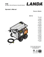
PRESSURE
W
ASHER
OPERA
TOR’S MANU
AL
89139430-7
Date Code
Serial No.
XXXXXX
Part No.
0000-0000.0
MAINTENANCE & SERVICE
the fuel solenoid valve functions properly. This can
be done by operating the machine and checking to
see that when the trigger on the spray gun is in the
off position, the burner is not firing.
Fuel Pressure Adjustment
To adjust fuel pressure, turn the adjusting screw
(located at the regulator pressure port) clockwise to
increase, counterclockwise to decrease. Do not exceed
200 psi.
NOTE:
When changing fuel pump, a by-pass
plug must be installed in return line port or fuel pump
will not prime.
Air Adjustment
Machines are preset and performance tested at the
factory - elevation 100' above sea level. A one-time ini-
tial correction for your location will pay off in economy,
performance, and extended service life. If a smoky or
eye-burning exhaust is being emitted from the stack,
two things should be checked. First, check the fuel to
be certain that kerosene or No. 1 home heating fuel
is being used. Next, check the air adjustment on the
burner. An oily, black, smoky fire indicates a lack of
air and the air band should be moved to allow the air
to flow through the burner. Sharp eye-burning white
fumes indicate too much air flowing through the com-
bustion chamber. The air band should be moved to
allow less air to flow through the burner.
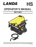
To adjust:
start machine and turn burner ON. Loosen
two locking screws found on the air band (refer to illus-
tration) and close openings until black smoke appears
from burner exhaust vent. Note air band position. Next,
slowly open the air band until white smoke just starts to
appear. Turn air band halfway back to the black smoke
position previously noted. Tighten locking screws.
Fuel
Use clean fuel oil that is not contaminated with water
and debris. Replace fuel filter and drain tank every
100 hours of operation. Use No. 1 or No. 2 Heating
Oil (ASTM D306) only.
NEVER
use gasoline in your
burner tank. Gasoline is more combustible than fuel
oil and could result in a serious explosion.
NEVER
use crankcase or waste oil in your burner. Fuel unit
malfunction could result from contamination.
Ignition Circuit
Periodically inspect wires, spring contact and elec-
trodes for condition, security and proper spacing.
Transformer test:
(CAUTION 10,000 VOLTS)
use
defect free insulated screwdriver and keep fingers off
blade! Lay blade across one contact: OK if arc will span
1/2" between end of blade and other contact.
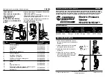
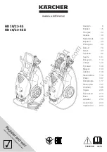
Electrode Setting:
(See illustration below)
Burner Nozzle
Keep the tip free of surface deposits by wiping it with
a clean, solvent-saturated cloth, being careful not to
plug or enlarge the nozzle. For maximum efficiency,
replace the nozzle each season.
Fuel Control System
The HS-3000 utilizes a fuel solenoid valve located on
the fuel pump to control the flow of fuel to the com-
bustion chamber. This solenoid, which is normally
closed, is activated by a flow switch when water is
flowing through it. When an operator releases the
trigger on the spray gun, the flow of water through the
flow switch stops, turning off the current to the fuel
solenoid. The solenoid then closes, shutting off the
supply of fuel to the combustion chamber. Controlling
the flow of fuel in this way gives an instantaneous burn
or no burn situation, thereby eliminating high and low
water temperatures, and combustion smoke normally
associated with machines incorporating a spray gun.
Periodic inspection is recommended to insure that
5/32" Gap
Nozzle
7/16"
Electrode
1/16"
Electrodes Check: Periodically check wiring connections.
If necessary to adjust electrodes, use diagram.
Air Band
Locking Screw
Air Band
Air Shutter
Locking Screw
Air Band
Locking Screw