Section 1: Assembly & Set-up
2/10/21
14
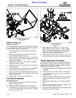
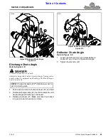
Discharge Chute Assembly
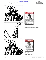
Figure 1-2
Discharge Chute
Refer to Figure 1-2:
1. Loosen the four rear bolts (#9) by two or three turns.
Do not remove bolts or nuts securing bolts.
2. Remove the four front bolts (#8), half-clamp
plate (#7), and half-spacer plate (#5) from discharge
spout (#1). Keep hardware for reuse.
3. Make sure bottom half-clamp plate (#4) is positioned
against underside of notched plate (#2). Being
careful not to damage plastic bearing (#11), slide
front of discharge chute (#1) onto notched plate (#2)
until discharge chute is centered over the notched
plate.
4. Place half-spacer plate (#5) on top of half-clamp
plate (#7) with bolt holes in alignment with each
other.
5. Position bottom half-clamp plate (#9) against
underside of notched plate (#2) as shown.
6. Bolt chute (#1) to half-spacer plate (#5) and half-
clamp plate (#7) with the four removed 1/4”-20 x 3/4"
GR5 cap screws (#8) and hex locknuts (#10).
7.
Draw all eight hex locknuts (#10) up snug and then
back each one off 1/2 turn.
35681
NOTE:
Half-clamp plate (#7) and half-spacer
plate (#5) are shipped bolted to discharge spout (#1).
IMPORTANT:
Be careful not to damage plastic
surface attached to underside of discharge chute
while attaching chute to the chipper’s notched plate.
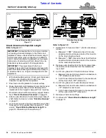
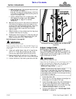
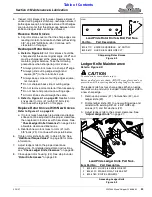
4" Feed Chute Assembly
Figure 1-3
Feed Chute
Refer to Figure 1-3:
WARNING
!
To avoid serious injury or death:
Keep yourself and others clear of the feed chute hinged area
while rotating the feed chute down. Body parts can be pinched
1. Remove nuts (#3) from bottom of feed chute (#1).
2. Hold feed chute (#1) up and pull linchpin (#4).
3. Rotate pivoting latch (#2) 90
o
clockwise and lower
feed chute (#1) down.
Refer to Figure 1-4 on page 15:
4. Insert linchpin (#4) in hole “A” to secure pivoting
latching in its rotated position.
5. Check ledger clearance before continuing. Refer to
“Check Ledger Knife Clearance”
6. Secure feed chute (#1) with two 1/2"-13 hex whiz
nuts (#3). Tighten nuts to the correct torque.
Inspect Twig Breaker Bar
The twig breaker bar (#5) should be inspected to make
certain it is centered in the rotor fin slots. See
on page 30 for detailed adjustment and
maintenance instructions.
35678

