Land Pride RTR05 Series Operator'S Manual Download Page 21

Section 2: Operating

Table of Contents

RTR0542 & RTR0550 Rotary Tillers 311-464M

3/2/22

17

WARNING

!

To avoid serious injury or death:  

Always disengage power take-off immediately after lifting 

tiller above ground level. Never operate tiller in the raised 

position. The tiller can discharge objects at high speeds 

resulting in injury or death.

Allow only persons to operate this implement who have 

fully read and comprehended this manual, and who have 

been properly trained in the safe operation of this 

implement. Serious injury or death can result from the 

inability to read, understand, and follow instructions 

provided in this manual.

Some tractors are equipped with two power take-off speeds. 

Be certain your tractor’s power take-off shaft is set-up to 

operate at 540 rpm. Do not exceed 540 rpm power take-off 

speed. Excessive speed can damage drive/driven 

components and increase the risk of a thrown object hazard.

Avoid exposure to dust containing crystalline silica 

particles. This dust can cause serious injury to the lungs 

(silicosis). Because crystalline silica is a basic component 

of sand and granite, many activities at construction sites 

produce dust containing crystalline silica. Trenching, 

sawing, and boring of material containing crystalline silica 

can produce dust containing crystalline silica.

IMPORTANT: 

Make sure all safety labels are in their 

proper location and in good condition before 

operation. Follow all directions on the safety labels.

IMPORTANT: 

To prevent damaging the park stand, 

always store the stand in its transport position before 

moving the tiller.

Transporting

WARNING

!

To avoid serious injury or death:  

When traveling on public roads, use LED lights, slow 

moving vehicle sign, clean reflectors, and other adequate 

devices to warn operators in other vehicles of your 

presence. If implement blocks visibility of slow moving 

vehicle sign, relocate sign so it is visible from the back at all 

times. Always comply with all federal, state, and local laws.

Always disengage power take-off and wait for the driveline 

to stop rotating before raising the implement to the 

transport position.

1. When raising tiller to transport position, be sure that 

the driveline does not contact tractor or tiller. Adjust 

the tractor’s 3-Point hitch lift height so that the tiller’s 

driveline is not lifted more than 25 degrees from 

horizontal to prevent damage to the driveline.

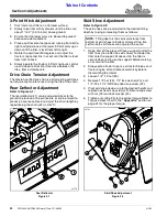
2. Remove park stand from its support tube, turn stand 

upside down and replace through top of support tube 

as shown in Figure 1-6 on page 13. Secure stand with 

wire retaining pin. Make certain wire retainer is 

caught over end of pin.

3. Be sure to reduce tractor ground speed when turning, 

and leave enough clearance so the tiller does not 

contact obstacles such as buildings, trees, or fences.

4. Select a safe ground travel speed when transporting 

from one area to another. When traveling on 

roadways, transport in such a way that faster moving 

vehicles may pass you safely.

5. When traveling over rough or hilly terrain, shift tractor 

to a lower gear.

Summary of Contents for RTR05 Series

Page 1: ...l Kit in French Language please see your Land Pride dealer Read the Operator s Manual entirely When you see this symbol the subsequent instructions and warnings are serious follow without exception Yo...

Page 2: ...ed the weights and measurements are no longer accurate for your machine Update the record by adding the machine weight and measurements provided in the Specifications Capacities Section of this manual...

Page 3: ...Torque Requirements 9 Tractor Shutdown Procedure 9 Park Stand Adjustment 10 3 Point Hitch Assembly 10 Driveline Installation 11 Deflector Chain 11 Tractor Hook Up 12 3 Point Category I Quick Hitch 12...

Page 4: ...pp on your smart phone open the App point your phone on the QR code and take a picture Dealer QR Locator The QR code to the left will link you to available dealers for Land Pride products Refer to Par...

Page 5: ...much experience they may have should carefully read this manual and other related manuals or have the manuals read to them before operating the power machine and this implement Thoroughly read and un...

Page 6: ...Remove all tools and unused parts from equipment before operation Do not weld or torch on galvanized metal as it will release toxic fumes Tire Safety Tire changing can be dangerous and must be perform...

Page 7: ...difficult to see especially at night Use the Slow Moving Vehicle SMV sign when on public roads Flashing warning lights and turn signals are recommended whenever driving on public roads Avoid High Pre...

Page 8: ...silica particles This dust can cause serious injury to the lungs silicosis There are guidelines which should be followed if crystalline silica quartz is present in the dust Be aware of and follow OSH...

Page 9: ...Important Safety Information 3 2 22 5 This page left blank intentionally...

Page 10: ...aler locator at www landpride com 3 Some new equipment installed during repair requires safety labels to be affixed to the replaced component as specified by Land Pride When ordering new components ma...

Page 11: ...ry Tillers 311 464M 3 2 22 7 23770 Reference RTR0542 RTR0550 Shown 23771 23760 23760 818 543C Danger Guard Missing Hazard Do not Operate 1 Place 70358 818 552C Danger Rotating Driveline Keep Away 1 Pl...

Page 12: ...with 540 rpm power take off speed and Category I 3 Point hitch on tractors in the 17 26 hp 12 7 19 4 kW range The RTR05 Series are Quick Hitch adaptable Reverse rotation tillers tend to achieve greate...

Page 13: ...ving the operator s seat 7 Use steps grab handles and anti slip surfaces when stepping on and off the tractor Dealer Preparations WARNING To avoid serious injury or death An unsupported parked tiller...

Page 14: ...es 14 2 Secure park stand in mounting bracket with 1 4 x 1 3 4 long wire lock pin 10 3 Point Hitch Assembly Refer to Figure 1 1 1 Attach 3 Point hitch Assembly 2 to inside of hitch plates with four 1...

Page 15: ...to the correct torque 4 Move driveline yoke back and forth to ensure that the driveline is secured to the gearbox input shaft 5 If not secured reattach the push pin and or bolt on yoke to the gearbox...

Page 16: ...1 Stabilize lower 3 Point arms to prevent side to side movement See your tractor Operator s Manual 2 Remove the two 5 16 linchpins 1 and hitch pins 2 3 Slowly back the tractor up to tiller until the...

Page 17: ...d in this manual before dismounting the tractor Select a safe ground speed that will allow adequate control of steering and stopping Never exceed 20 mph 32 km h with attached equipment Rough terrain r...

Page 18: ...to fit all applications IMPORTANT The power take off shaft and gearbox input shaft must be aligned and level with each other when checking driveline minimum length A driveline that is too long can da...

Page 19: ...er the support blocks and lower it onto the blocks b Shut tractor down before dismounting Refer to Tractor Shutdown Procedure on page 9 c Move or remove the drawbar if it interferes with the implement...

Page 20: ...ts Page 25 Check oil level in gearbox Make sure all plugs have been replaced when completed Refer to Gearbox lubrication Page 26 Check tiller initially and periodically for loose bolts and pins Refer...

Page 21: ...n Follow all directions on the safety labels IMPORTANT To prevent damaging the park stand always store the stand in its transport position before moving the tiller Transporting WARNING To avoid seriou...

Page 22: ...Adjustment steps on page 20 when repositioning the skid shoes 7 Pull back on the driveline pull collar and hold while pulling the driveline yoke from the tractor s power take off shaft 8 Collapse driv...

Page 23: ...un in the clutch if your model is equipped with one and gone through the Operating Checklist If you have missed any of these steps please complete them before proceeding Now that you have properly pre...

Page 24: ...soil texture or can be raised to produce a coarse soil texture Adjust the chain length by repositioning the chain 2 in slot A Rear Deflector Figure 3 1 23778 23778 Skid Shoe Adjustment Refer to Figure...

Page 25: ...ractor is started and the power take off is engaged WARNING To prevent serious injury or death Always follow Tractor Shutdown Procedure provided in this manual before dismounting the tractor Do not op...

Page 26: ...gearbox input shaft before reattaching the driveline to the gearbox Refer to Gearbox Input Shaft on page 26 Spring Loaded Slip Clutch With Bolt on Yoke Figure 4 2 Driveline With Slip Clutch Refer to...

Page 27: ...ording each spring length before disassembling the clutch Refer to Figure 4 5 on page 23 4 Remove spring retainer nuts 9a springs 2 and bolts 9b from the assembly 5 Each friction disk 5 must then be s...

Page 28: ...ose 2 Check the tines for wear and replace if necessary See Tine Replacement earlier in this section 3 Inspect the tiller for loose damaged or worn parts and adjust or replace if needed 4 Repaint part...

Page 29: ...e and then reassemble Type of grease Multi Purpose Quantity Coat Generously Chaincase Type Recommended Shell Alvania EP00 Oil Alternate SAE 90 wt oil Quantity As required IMPORTANT Tiller should be le...

Page 30: ...eration Check oil level in gearbox by removing the center plug at the rear of the box Oil should come to bottom of center plug Type of Lubrication SAE 80 90W EP Oil Quantity Refer to Gearbox lubricati...

Page 31: ...blades Skid shoes Adjustable Storage stands Adjustable Rear deflector Adjustable Driveline Category II Off Center Shear bolt standard Slip Clutch optional Gearbox hp kW 26 hp 19 4 kW input at 540rpm 1...

Page 32: ...djustable park stand Allows for easy hook up and storage Adjustable skid shoes Control depth with seven adjustments Formed rear deflector Keeps dirt in and leaves a level finish Forming gives deflecto...

Page 33: ...worn or bent Tines are incorrectly installed Obstacles are entangled in tines and or rotor Lower hitch clevises are in the wrong position Lower tractor 3 Point arms Increase tractor rpm Adjust skid sh...

Page 34: ...0 230 170 325 240 M18 X 2 5 195 145 310 230 405 300 3 4 10 235 170 360 265 510 375 M18 X 1 5 220 165 350 260 485 355 3 4 16 260 190 405 295 570 420 M20 X 2 5 280 205 440 325 610 450 7 8 9 225 165 585...

Page 35: ...suse also specifically includes failure to properly maintain oil levels grease points and driveline shafts Claims under this Warranty should be made to the dealer which originally sold the product and...

Page 36: ...Corporate Office P O Box 5060 Salina Kansas 67402 5060 USA www landpride com...

Reviews: