22
Section 3: Operating Instructions
RCR1884 Series Rotary Cutter 312-880M
2/03/12
Table of Contents
Blade Engagement & Disengagement
Cutter blades can lock-up against each other during
start-up and shut-down especially if the tractor’s PTO
engagement is “INSTANT ON” and “INSTANT OFF”.
Following Blade Engagement and Blade Disengagement
instructions on page 22 will help eliminate blade lock up.
Blade Engagement
1.
Increase throttle to a speed just enough to get the
cutter started without stalling tractor while slowly
engaging PTO drivelines. Use tractor’s PTO soft start
option if available.
2.
Ensure that all power shafts are rotating and that the
cutter is not vibrating excessively after ramping up to
PTO speed for at least 3 seconds. If excessive
vibration continues after 3 seconds at full PTO
speed, disengage PTO immediately, shut down
tractor, and remove switch key.
3.
Check blades for a lock-up situation. Block cutter
deck up before working under the unit. Unlock
blades, remove support blocks, and repeat “Blade
Engagement” instructions.
Blade Disengagement
1.
Slowly decrease throttle speed until engine idle
speed is reached and then disengage PTO.
2.
Engage tractor park brake, shut tractor engine off
and remove switch key. Stay on tractor until blades
have come to a complete stop.
Field Operation
!
WARNING
Clear area to be cut of debris and other unforeseen removable
objects before cutting. Mark any potential hazards that cannot
be removed such as tree stumps, post, rocks, holes, and drop-
offs with a visible flag.
IMPORTANT: Maintain correct PTO speed. Loss of
PTO speed will allow blades to swing back resulting
in a ragged, uneven cutting. Excessive engine speed
will cause damage to the power train components.
IMPORTANT: Your Rotary Cutter is equipped with
free swinging cutting blades to reduce shock loads
when striking obstacles. However, it is best to avoid
striking obstacles to extend cutter and blade life.
1.
Thoroughly inspect area to be cut for debris and
unforeseen objects. Mark any potential hazards.
2.
Follow “Blade Engagement” instructions on this
page to start cutter blades turning.
3.
Optimum ground speed depends on density of
material being cut, horsepower rating of tractor, and
terrain. Always operate tractor at cutter’s full rated
PTO speed in a gear range that allows the cutter to
make a smooth cut without lugging tractor down,
usually between 2 to 5 mph.
4.
Stop traveling and disengage PTO after the first 50
feet of cutting. Check cutter levelness and cutting
height to make certain it is adjusted properly.
5.
Do not engage PTO with 3-Point cutter fully raised.
6.
Periodically disengage PTO, shut down tractor,
remove key, and check for foreign objects wrapped
around the blade spindle. Block cutter deck up before
removing objects.
7.
Frequently inspect cutter for loose bolts and nuts.
Tighten all loose bolts and nuts as indicated in the
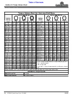
“Torque Values Chart” on page 34.
8.
For additional information, see “General Operating
Instructions” on page 23.
Un-hooking the Rotary Cutter
Un-hook Rotary Cutter from the tractor as follows:
1.
See “Long Term Storage” on page 27 if cutter is to
be stored for a long time.
2.
Park on a level solid surface and lower deck to
ground level or onto support blocks.
3.
Engage tractor park brake, shut tractor engine off,
and remove switch key. Stay on tractor until blades
have come to a complete stop.
4.
Disconnect driveline and safety chain from tractor.
5.
Unhook 3-Point hitch from tractor and drive tractor
forward several feet.
6.
Reinstall hitch pins, linch pins, and hair pin cotters in
cutter hitch for safe keeping.
7.
Collapse driveline by pushing tractor end of driveline
towards cutter gearbox.
8.
Support collapsed driveline off the ground.
NOTE: Do not cut in wet conditions. Wet material
will build up on the deck underside creating poor
discharge, high wear, and additional horsepower.
Periodically disengage PTO, turn off tractor, remove
key & check for objects wrapped around blade
spindle. Block deck up before removing objects.
Frequently inspect cutter for loose bolts and nuts.
Tighten all loose hardware as indicated in the
“Torque Values Chart” on page 34.


