


Section 5: Maintenance & Lubrication
7/13/20
RCD1884 Rotary Cutters 326-355M
27
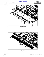
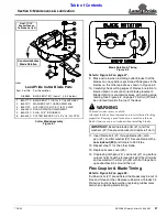
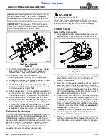
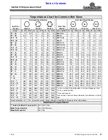
Cutter Blade Assembly
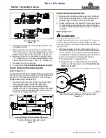
Figure 5-1
33002
Counterclockwise
Blade Rotation
Use 1-11/16"
Socket Wrench
On Blade Nut (#3)
Land Pride Cutter Blade Parts
Item Part No. Part Description
318-586A BLADE BOLT KIT (items 1, 2, & 3 below)
1 802-277C BLADE BOLT 1 1/8-12 x 3 7/16 WITH KEY
2 804-147C WASHER FLAT 1 HARD ASTMF436
3 803-170C NUT HEX TOP LOCK 1 1/8-12 PLATE
4 326-234H ROUND DISHPAN WELDMENT
5 840-273C PLUG LP 3" ID RUBBER
6 820-443C CUTTER BLADES 1/2" x 4" x 16" LG. CCW
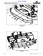
Blade Rotation & Timing
Figure 5-2
Refer to Figure 5-2 on page 27:
9. Make certain when installing cutter blades that the
blades on one spindle is positioned 90 degrees to the
blades on the other spindle as shown in Figure 5-2.
10. Carefully check cutting edges of blades in relation to
blade rotation to ensure correct blade placement.
Blade rotation is counterclockwise with cutting edge
leading. See Figure 5-2 on page 27. Airfoil (lift) must
be oriented towards the top of the deck.
WARNING
!
To avoid serious injury or death:
A locknut that has been removed can lose its thread locking
properties. Reusing a used locknut can result in a thrown
blade. Always use a new locknut when installing blades.
11. Insert blade bolt (#1) through blade (#6), dish
pan (#4), and flat washer (#2). Secure blade with a
new locknut (#3)
and torque to 450 ft-lbs.
12. Repeat step 11 for the other blade.
13. Replace access cover (#5).
14. If replacing dishpan (#4), castle nut (#7) on gearbox
output shaft should be torqued to 450 ft-lbs. minimum
and secured with cotter pin (#8) with both legs bent
opposite directions around the nut.
Flex Coupler & Blade Timing
Refer to Figure 5-3 on page 28:
If rubber discs (#7) are wrinkled, the blades may be out of
time and hit each other. Replace rubber disc if blades hit.
Follow instructions below when replacing rubber discs
and when adjusting blade timing.


