background image

27

Section 5: Maintenance & Lubrication

2/02/08

RC5014 (540 RPM) and RCM5014 (1000 RPM) Rotary Cutters   330-117M

Land Pride

Table of Contents

Type B Clutches

Clutch Run-In

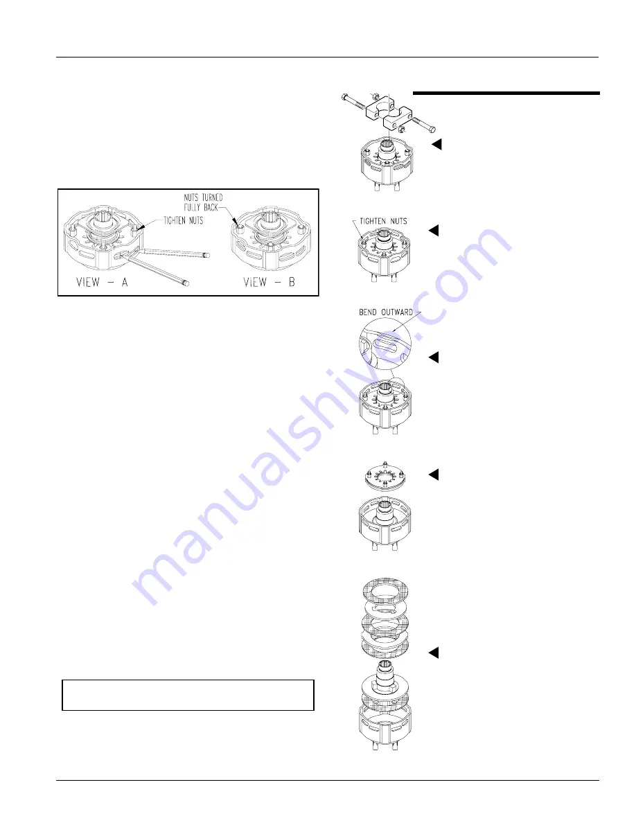
Refer to Figure 5-8 (View - A):

1.

Using a pencil or other marker, scribe a line across the
exposed edges of the clutch plates and friction disks.

2.

Tighten all 4 nuts uniformly until spring load is low
enough that the clutch slips freely with PTO
engaged.

Type B Clutch Run-In

Figure 5-8

3.

Make sure the area is clear of all bystanders and
machine is safe to operate.

4.

Start tractor and engage PTO for 2-3 seconds to
permit slippage of clutch surfaces. Disengage PTO,
then re-engage a second time for 2-3 seconds.
Disengage PTO, shut off tractor and remove key.
Wait for all components to stop before dismounting
from tractor.

5.

Inspect clutch and ensure that the scribed markings
made on the clutch plates have changed position.
Slippage has not occurred if any two marks on the
friction disk and plate are still aligned. A clutch that
has not slipped must be disassembled to separate
the friction disk plates. See “Clutch Disassembly,
Inspection & Assembly” below.

Refer to Figure 5-8 (View - B):

6.

If no two marks on the friction disk and plate are still
aligned, Turn all 4 nuts fully back.

7.

Allow clutch to cool to ambient temperature before
operating again. Clutch is now ready for use.

8.

The clutch should be checked during the first hour of
cutting and periodically each week. An additional set
of scribe marks can be added to check for slippage.

Clutch Disassembly, Inspection & Assembly

If clutch run-in procedure above indicated that one or more
of the friction disks did not slip, then the clutch must be
disassembled to separate the friction disks.

23696

NOTE: Before proceeding, secure clutch firmly in a
vise or other clamping device to prevent injury.

Step 2

Tighten the four hex nuts
uniformly until the clutch pack
and hub are loose.

Step 3

Bend all four retaining lugs
out on edge of clutch housing.

Step 4

Remove thrust plate with
Belleville Springs and lug
rings to access friction discs
and hub for inspection or
service.

4-Plate Disassembly

Step 1

If included, remove end half
clamps.

Step 5

Inspect friction discs and hub.

23553

Summary of Contents for RC5014

Page 1: ... Read the Operator s manual entirely When you see this symbol the subsequent instructions and warnings are serious follow without exception Your life and the lives of others depend on it Table of Contents RC5014 540 RPM and RCM5014 1000 RPM Rotary Cutters Operator s Manual 330 117M 24837 2 02 08 ...

Page 2: ...s 12 Standard Clevis Hitch 12 Pintle Hitch Optional 12 Hitch Assembly 12 Wing Axle Assembly 12 Tractor Hook up 13 Driveline Installation 13 Check Driveline Length 14 Hydraulic Hook up 14 Unhooking From the Cutter 15 Section 2 Adjustments 16 Center and Wing Section Leveling 16 Cutting Height Adjustment 16 Section 3 Operating Instructions 17 Pre Start Checklist 17 Inspection Procedures 17 Transport ...

Page 3: ...ement at any time Look For The Safety Alert Symbol The SAFETY ALERT SYMBOL indicates there is a potential hazard to personal safety involved and extra safety precaution must be taken When you see this symbol be alert and carefully read the message that follows it In addition to design and configuration of equipment hazard control and accident prevention are dependent upon the awareness concern pru...

Page 4: ...hts and turn signals are recommended whenever driving on public roads Use lights and devices provided with implement Practice Safe Maintenance Understand procedure before doing work Use proper tools and equipment refer to Operator s Manual for additional information Work in a clean dry area Lower the implement to the ground put tractor in park turn off engine and remove key before performing maint...

Page 5: ...s or thrown from the machine Never allow children to operate equipment Tire Safety Tire changing can be dangerous and should be preformed by trained personnel using the correct tools and equipment When inflating tires use a clip on chuck and extension hose long enough to allow you to stand to one side and NOT in front of or over the tire assembly Use a safety cage if available When removing and in...

Page 6: ... clean and legible 2 Replace all damaged or missing labels To order new labels go to your nearest Land Pride dealer 3 Some new equipment installed during repair requires safety labels to be affixed to the replaced component as specified by Land Pride When ordering new components make sure the correct safety labels are included in the request 4 Refer to this section for proper label placement To in...

Page 7: ...y Information 2 02 08 RC5014 540 RPM and RCM5014 1000 RPM Rotary Cutters 330 117M Land Pride Table of Contents 24846 24844 24845 23571 818 552C Danger Rotating Driveline Entanglement Hazard ROTATING DRIVELINE KEEP AWAY ...

Page 8: ...0 RPM and RCM5014 1000 RPM Rotary Cutters 330 117M 2 02 08 Land Pride Table of Contents 23571 23594 24844 24846 818 543C Danger Guard Missing DO NOT Operate 2 places 818 540C Danger Shield Missing DO NOT Operate Wing Driveline Main Driveline ...

Page 9: ...s 330 117M Land Pride Table of Contents 24844 24844 24844 24844 818 276C Warning Rotating Blade Hazard TRACTOR MUST HAVE SAFETY GUARDING 818 840C Danger Rollover Hazard 818 561C Warning Raised Wing Hazard Located on Left Wing Right Wing 818 830C Safety Combo Located on Left Wing Right Wing ...

Page 10: ...rs 330 117M 2 02 08 Land Pride Table of Contents 838 588C Warning Folding Cutter Speed Warning 838 094C Warning High Pressure 24844 24844 24846 24846 818 556C Danger Thrown Object Hazard Located on Left Wing Right Wing 818 564C Danger Rotating Blade Located on Left Wing Right Wing ...

Page 11: ...02 08 RC5014 540 RPM and RCM5014 1000 RPM Rotary Cutters 330 117M Land Pride Table of Contents 24846 24853 818 229C Amber Reflector Located on Left Wing Right Wing 818 230C Red Reflector Located on Right Wing and Weight Box 24845 24844 ...

Page 12: ...sing quality materials Proper assembly maintenance and safe operating practices will help you get years of satisfactory use from this machine The parts on your Rotary Cutter have been specially designed and should only be replaced with genuine Land Pride parts Therefore should your Rotary Cutter require replacement parts go to your Land Pride Dealer Application The heavy duty RC5014 and RCM5014 Se...

Page 13: ... parts and equipment readily at hand Torque Requirements Refer to Torque Values Chart on page 40 to determine correct torque values when tightening hardware Pre Assembly Checklist Check Reference Have a fork lift or loader with properly sized chains and safety stands capable of lifting and supporting the equipment on hand Have a minimum of two people available during assembly Make sure all major c...

Page 14: ... 4 x 1 1 2 clevis pin 6 3 4 flat washer 4 and 5 32 x 1 1 4 cotter pin 5 2 Install left and right leveling rods 2 to hitch frame 3 with 3 4 x 1 1 2 clevis pins 6 3 4 flat washes 4 and 5 32 x 1 1 4 cotter pins 5 Final adjustment should be made when the cutter is attached to the tractor 3 Install parking jack 7 to hitch frame 3 and secure with attached pin 8 Adjust parking jack to preferred drawbar h...

Page 15: ...rn Tighten jamb nut 10 against nut 2 7 Lower jack stand 3 until hitch weight is supported by drawbar Remove jack stand from hitch and store on weight box storage base Prevent water and freeze damage by storing it so that the foot is level or lower than the head See cover picture for correct position 8 Attach hitch safety chain 4 to the tractor Adjust chain length to remove all slack except what is...

Page 16: ...TANT The Rotary Cutter must be hitched to the tractor with tractor and cutter aligned in a straight line on a level surface This arrangement will provide the correct alignment between tractor PTO shaft and gearbox input shaft IMPORTANT Two or three small chains are supplied with each driveline These chains must be attached to outer and inner driveline shields and to cutter and tractor to restrict ...

Page 17: ...or length if driveline interferes See Figure 1 1 on page 11 for correct drawbar dimensions Unhooking From the Cutter 1 Park cutter on a level solid hard surface Place tractor gear selector in park and set park brake Refer to Figure 3 2 on page 18 2 Raise wing up in the transport position and place transport lock bar in the locked position Make sure transport bar is secured in place with lock pin 2...

Page 18: ... nuts 4 at the same time until the right and left hand sides are inclined from front to back by 1 5 Be sure that both sides are equal distance from ground line to center line of hinge rod and that left and right leveling rods have equal tension Re tighten jam nut 3 6 Lower wing to ground position Wing section will need adjusting if wing top deck sheet is not level with center top deck sheet Level ...

Page 19: ...Refer to Section 3 Operating Instructions Page 17 Read and follow all Maintenance Instructions Refer to Section 5 Maintenance Lubrication Page 24 Read and follow all Lubrication Instructions Refer to Lubrication Points Page 30 Make sure all gearboxes are properly lubricated Refer to Gearbox lubrication Page 31 Check cutter initially and periodically for loose bolts and pins Refer to Torque Values ...

Page 20: ...or adequate warning to operators of other vehicles Comply with all federal state and local laws 1 Select a safe ground speed when transporting from one area to another 2 Be sure to reduce tractor ground speed when turning and leave enough clearance so the cutter does not contact obstacles such as buildings trees or fences 3 Always raise the wing and set the transport lock to keep wing decks from f...

Page 21: ... that all power shafts are rotating and that the cutter has no vibration 8 Continue to increase throttle to full 540 or 1000 PTO speed before commencing forward operation 9 While cutting use the lever for the hydraulic lift cylinder to set the cutter to correct cutting height 10 Once cutting height has been set stop traveling disengage driveline shut tractor engine off and remove switch key Do not...

Page 22: ...ting in serious injury or death DANGER Rotary cutters have the ability to discharge objects at high speeds To prevent personal injury caused by thrown objects the use of front rear safety guards is strongly recommended WARNING Tractor PTO shield all Rotary Cutter gearbox shields and driveline shields must be in place and secured while the cutter is operating to avoid injury or death from entanglem...

Page 23: ...s to the right and to then the left to ensure that the rear tractor tires do not contact the deck or hitch You should now be ready to move to the cutting site to begin mowing You should have inspected and should only be cutting in an area you are familiar with which is relatively free of debris and unseen objects Never assume an area is clear and extremely tall grass should be cut twice to detect ...

Page 24: ...on 6 x 21 Laminated Tires are constructed of laminated layers of solid rubber that will never go flat 24 x 7 75 x 15 Used Aircraft Tires without foam filling are built tough to withstand the rugged use a cutter receives and to provide a smoother ride when transporting from field to field 24 x 7 75 x 15 Used Aircraft Tires with foam filling have the same features as the Aircraft Tires without foam ...

Page 25: ... Selector Control Valve Kit This kit is for tractors needing only one additional duplex outlet It converts one of the tractor s duplex outlets into two duplex outlets with a control valve A selector switch on the control valve selects which of the two duplex outlets is operational with the tractor hydraulic control lever See your local Land Pride dealer if your tractor is not properly equipped wit...

Page 26: ... removing access cover 7 IMPORTANT Replace cutting blades with genuine Land Pride blades only Blades must be replaced in mating pairs Not replacing both blades will result in an out of balance condition that will contribute to premature bearing breakdown on the spindle hub and create structural cracks in cutter housing Always inspect cutting blades before each use Make certain they are properly in...

Page 27: ... output shaft should be torqued to 550 ft lbs minimum and secured with cotter pin 9 with both legs bent opposite directions around the nut 11 Replace access cover 7 with flat washers 10 lock washers 11 and wing nuts 12 12 Reconnect main driveline to tractor PTO shaft Drivelines With Slip Clutches CAUTION Engage parking brake disengage PTO shut off tractor and remove key before working on or around...

Page 28: ...rks can be added to check for slippage See Figure 5 7 to adjust spring length Clutch Disassembly Inspection Assembly Refer to Figure 5 7 If clutch run in procedure above indicated that one or more friction disks did not slip then the clutch must be disassembled to separate the friction disks Disassembly 13693 IMPORTANT Not all Type A clutch components are arranged as illustrated in Figure 5 6 Also...

Page 29: ... has not slipped must be disassembled to separate the friction disk plates See Clutch Disassembly Inspection Assembly below Refer to Figure 5 8 View B 6 If no two marks on the friction disk and plate are still aligned Turn all 4 nuts fully back 7 Allow clutch to cool to ambient temperature before operating again Clutch is now ready for use 8 The clutch should be checked during the first hour of cu...

Page 30: ...e inadequate operation of cutter and create a safety hazard There are two skid shoes mounted on either side of the center section and one skid shoe mounted on each wing section Check all skid shoes for wear and replace if necessary Order only genuine Land Pride parts from your local Land Pride Dealer Center Skid Shoe Refer to Figure 5 9 Replace center skid shoes as follows 1 Remove 1 2 13 hex whiz...

Page 31: ...e cuter is ready for field use the next time you hook up to it DANGER Always disconnect main driveline from tractor PTO and secure cutter deck in the up position with solid supports before servicing the underside of the cutter 1 Clean off any dirt and grease that may have accumulated on the cutter and moving parts Scrape off compacted dirt from the bottom of deck and then wash surface thoroughly w...

Page 32: ...ease fitting The relief hole releases pressure from inside the hub casting when it is greased The hub should be greased until grease purges from the relief hole Adjustable Turnbuckle Type of Lubrication Multi Purpose Grease Quantity As required Lubrication Points 50 hrs Multi purpose spray lube Multi purpose grease lube Multi purpose oil lube Intervals in hours at which lubrication is required Lub...

Page 33: ... and screw it back in without tightening Unscrew dipstick and check oil level mark If low fill through top plug hole in gearbox with EP 80 90W oil until oil reaches full mark on the dipstick Reinstall vent plug with dipstick and tighten Take your gearbox to a Land Pride dealer if it requires service Type of Lubrication Gear Lube 80 90W EP Quantity Fill until oil reaches full mark on dipstick IMPOR...

Page 34: ...xternal profile tube grease point Zerk located through slot in plastic outer tubes 23566 Drivelines with internal profile tube grease point Zerk Located on end of plastic outer tube Conventional Driveline Joints Shields Type of Lubrication Multi purpose Grease 8 Hrs 23567 Drivelines with external profile tube grease point 23566 Drivelines with internal profile tube grease point 23563 20182 Interme...

Page 35: ...member and must be greased every 8 hours to prevent premature failure of the joint Grease fittings are located on the u joints and driveline shields and should be lubricated every 8 hours of operation NOTE To extend the life of the constant velocity joint extensive lubrication must be performed every 8 hours of operation 15312 8 Hrs 23565 Drivelines with internal tube grease point 15312 23565 Driv...

Page 36: ...Quantity Coat Generously 14618 20 Hrs Wing Driveline Joints Shields Type of Lubrication Multi purpose Grease 13755 8 Hrs 23563 Drivelines with internal profile tube grease point Drivelines with external tube grease point Zerk located through slot in tubes Zerk Located on end of plastic outer tube Drivelines with external profile tube grease point 23563 Drivelines with internal profile tube grease ...

Page 37: ...and stroke control spacers Deck Material Thickness 3 16 Side Skirt Thickness 1 4 Skid Shoes Wing and Weight Box Reversible replaceable Center Deck 2 Replaceable Blades 4 2 per Carrier 1 2 x 4 Thru harden free swinging alloy steel with uplift Blade Overlap 6 Blade Bolt Keyed with hardened flat washer lock nut Blade Holder 3 16 Round bolt on stump jumper with 1 diamond shaped blade bar Deck Ring Opt...

Page 38: ... 330 117M 2 02 08 Land Pride Table of Contents 14 7 19 3 3 6 1 8 9 9 3 4 26846 26844 8 9 9 8 5 8 Transport Width With Wing Axles Disconnected At The Turnbuckles And Wheels Folded Back See Figure 1 5 on page 12 Transport Width With Wing Axles Connected At The Turnbuckles At 2 Cutting Height ...

Page 39: ...ck loads and harsh mowing conditions Easy greasable drivelines Drivelines have access holes for greasing the U joints in the driveline and to grease the inner profiles 4 Plate slip clutch Protects drivelines and gearboxes by slipping clutches rather than twisting the driveline when impacts are encountered Keyed blade bolt Makes removing the cutting blades easier Thru harden blades Provides longer ...

Page 40: ...e wheel rims 5 Square rear axle tubing Heavy axle to handle harsh conditions Spring cushioned center axle Protects unit from bumps and ground shock Replaceable wheel spindles Wheel spindles can be replaced when damaged without replacing the entire axle Simply remove two bolts to replace damaged spindle Features and Benefits Of Optional Equipment 5 or 6 Wheel option Outer wing wheel can be single 5...

Page 41: ...ine shaft telescoping tube failing Avoid hitting solid objects Driveline shaft telescoping tube wearing Lubricate every 20 hours of operation Blades wearing excessively Raise cutting height Blades coming loose Tighten blade hardware refer to Service Cutting Blades in the Maintenance and Lubrication section starting on page 24 Blades breaking Avoid solid objects Loose blade carrier Tighten shaft nu...

Page 42: ...265 510 375 M18 X 1 5 220 165 350 260 485 355 3 4 16 260 190 405 295 570 420 M20 X 2 5 280 205 440 325 610 450 7 8 9 225 165 585 430 820 605 M20 X 1 5 310 230 650 480 900 665 7 8 14 250 185 640 475 905 670 M24 X 3 480 355 760 560 1050 780 1 8 340 250 875 645 1230 910 M24 X 2 525 390 830 610 1150 845 1 12 370 275 955 705 1350 995 M30 X 3 5 960 705 1510 1120 2100 1550 1 1 8 7 480 355 1080 795 1750 1...

Page 43: ...h has been repaired or altered in a way which adversely affects its performance or reliability or which has been used for a purpose for which the product is not designed Misuse also specifically includes failure to properly maintain oil levels grease points and driveline shafts Claims under this Warranty should be made to the dealer which originally sold the product and all warranty adjustments mu...

Page 44: ...Corporate Office P O Box 5060 Salina Kansas 67402 5060 USA ...

Reviews: