lancer Sensation 30 Installation Manual Download Page 6

6

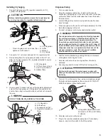
Adjust Water Flow Rate & Syrup/Water Ratio

1. 

Remove valve cover from first valve.

2. 

Close syrup shut-off at mounting block for first valve. 

4.  Remove nozzle by twisting counter clockwise and pulling 

down, then remove diffuser by pulling down.


Ensure there is ice on the cold plate and the lines are 

cold before attempting to set the flow rates on the 

valves. The drink temperature should be no higher than 

40°F (4.4°C) when flow rates are set. 

NOTE

A

B

Increase

Decrease

C

E

A. Flow Control, Water

B. Flow Control, Syrup

C. Nozzle (Diffuser inside)

D. Retainer Clip

E. Soda Lever

D

A

B

A. Syrup Seperator

B. Soda Lever

A

B

A. Water ON

B. Syrup Closed

A

B

A. Nozzle

B. Diffuser

C. Soda Lever

C

A

B

C

A. Syrup Seperator

B. Ratio Cup

C. Verify Soda/

    Water Level

6. 

Re-open syrup shut-off at mounting block.

7. 

Activate valve to purge syrup until steady flow is achieved.

8.  Using a Lancer brix cup, activate the valve and capture a 

sample. Verify that the syrup level is even with the water 

level. Use a screwdriver to adjust if needed. 

9.  Remove syrup seperator and reinstall nozzle. Replace valve 

cover.

10. 

Repeat steps 1-8 for each valve. 

11. 

Re-install merchandiser, splash plate, and top cover.

12.  Activate each valve until the carbonator pump comes on. 

Release the button, allow carbonator to fill and stop. Repeat 

this process until a steady flow of carbonated water is 

achieved. 

13.  Activate each valve to purge air from the syrup lines.


The pump deck has a 3 minute timeout feature. If the


timeout occurs, turn the deck OFF then ON by flipping


the switch on the control box.

NOTE


To check for CO

2

 leaks, close the valve on the CO

2


cylinder and observe if the pressure to the system 


drops with the  cylinder valve closed for five minutes. 


Open the cylinder valve after check.

NOTE

3. 

Using a Lancer ratio cup verify water flow rate (5 oz. in 4 

sec.). Use a screwdriver to adjust if needed.

5.  Install Lancer (yellow) syrup seperator 

(PN 54-0031)

 in place 

of nozzle.

Summary of Contents for Sensation 30

Page 1: ... your convenience scan this QR code with a mobile device app required for immediate access to other Technical Documents and alternative translations if available pertaining to this unit Contact Lancer Customer Service for assistance as required The dispenser is for indoor use only This unit is not a toy Children should not be supervised not to play with appliance It should not be used by children ...

Page 2: ...35 lbs 152 kg Empty 275 lbs 125 kg Ice Capacity 250 lbs 113 6 kg Ice Dispensable 185 lbs 84 kg CARBON DIOXIDE CO2 SUPPLY Min Pressure 70 PSIG 0 483 MPA Max Pressure 80 PSIG 0 552 MPA FITTINGS Carbonator Inlet 3 8 inch barb Plain Water Inlet 3 8 inch barb Brand Syrup Inlets 3 8 inch barb ELECTRICAL 115 VAC 60 Hz 3 0 Amps PLAIN WATER SUPPLY Min Flowing Pressure 75 PSIG 0 516 MPA CARBONATED WATER SUP...

Page 3: ... accessibility of installed equipment refer to 2010 ADA Standards for Accessible Design http www ada gov NOTE The drain spider is located to the right side near the front of the bin under the ice shroud The coldplate has a cavity designed to hold the drain spider During shipment the drain spider may become dislodged from its original position Prior to installing the unit ensure the drain spider is...

Page 4: ...your IBD s warranty but will result in the inability to control the level of ice in the ice bin which can cause damage to your dispenser ATTENTION 4 Attach Bin Stat Bracket As Shown Recommended Bin Stat Attachment Bulb Tube 5 Ensure the icemaker is installed properly to allow for removal of the Merchandiser 6 Ensure manual fill is accessible 7 Clean and maintain icemaker per manufacturer s instruc...

Page 5: ...lve cap lever Hold open until water flows from the relief valve then close flip down the relief valve 3 Verify all Bag In Box contains syrup and check all connec tions for leaks 4 Place enough ice in the ice bin to fill approximately 1 2 of the bin before plugging in the unit 5 Connect unit power cord to grounded electical outlet The dispenser must be properly electrically grounded to avoid seriou...

Page 6: ...cer brix cup activate the valve and capture a sample Verify that the syrup level is even with the water level Use a screwdriver to adjust if needed 9 Remove syrup seperator and reinstall nozzle Replace valve cover 10 Repeat steps 1 8 for each valve 11 Re install merchandiser splash plate and top cover 12 Activate each valve until the carbonator pump comes on Release the button allow carbonator to ...

Page 7: ... one ounce of cleaner to two gallons of water Prepare a minimum of five gallons of cleaning solution Do not use abrasive cleaners or solvents because they can cause permanent damage to the unit Ensure rinsing is thorough using clean potable water at a temperature of 90 F to 110 F Extended lengths of product lines may require additional cleaning solution 1 Clean cloth towels 2 Bucket 3 Extra nozzle...

Page 8: ...up system again A B C A Nozzle B Diffuser C Soda Lever Refer to the Automatic Agitation Warning on the first page of this manual NOTE It is recommended to perform this procedure monthly or more often if desired Use the cleaning solution described on page 7 An alternate solution of one part water to one part vinegar may be used to remove water spots and calcium deposits NOTE Always remove the ice c...

Page 9: ...anitizing Syrup Lines Bag in Box 1 Disconnect syrup lines from BIB s 2 Place syrup lines with BIB connectors in a bucket of warm water 3 Activate each valve to fill the lines with warm water and flush out syrup remaining in the lines 4 Prepare Cleaning Solution described on previous page 5 Place syrup lines with BIB connectors into cleaning solution 6 Activate each valve until lines are filled wit...

Page 10: ...10 WIRING DIAGRAMS Sensation 30 115 Volt Wiring Diagram ...

Page 11: ...SW2 SWITCH 1 MUST BE ON FOR CORRECT OPERATION 2 1 6 SW1 SWITCH 2 LOW ICE ALARM ENABLED 5 8 3 6 8 7 3 8 ON SW2 SW1 6 5 LANCER PN 06 3289 3 SW1 7 1 6 4 2 SW1 SWITCH 1 LOW ICE LED INDICATOR ENABLED 1 4 2 3 1 2 8 1 SWITCH REFILL START AFTER 7 8 OFF OFF 6 SEC DISPENSED OFF ON 9 SEC DISPENSED ON OFF 12 SEC DISPENSED ON ON 15 SEC DISPENSED SWITCH REFILL ON TIME 5 6 OFF OFF 11 SECONDS OFF ON 9 SECONDS ON ...

Page 12: ...Lancer Corp 800 729 1500 Technical Support Warranty 800 729 1550 custserv lancercorp com lancercorp com ...

Reviews: