3
INSTALLATION
Unpack the Dispenser
1. Cut package banding straps and remove.
2. Open the box and remove the accessory kit and loose parts.
3. Carefully remove the dispenser from the corrugated shipping
carton and place on a flat surface taking care to not scratch
the plastic covers.
Inspect unit for concealed damage. If evident, notify
delivering carrier and file a claim against the same.
NOTE
Selecting/Preparing Counter Location
3. Select a location for the remote chiller system or carbonator
(if necessary), syrup pumps, CO
2
tank, product containers,
and water filter (recommended).
4. Using Counter Cutout Template provided, cut out required
opening for the drip tray and tower installation in the
designated dispenser location.
Dispenser/Chiller Installation
1. Carefully lift unit and using a screwdriver, separate the
mounting plate from the tower and drip tray.
2.
Remove the drain fitting from the drip tray. First, unscrew the
lower section then press firmly from the bottom to remove
the upper portion of the drain fitting.
3. Using the six (6) mounting screws provided, secure the
mounting plate to the counter top.
4. Using proper lifting techniques, lift the tower over the counter
top and slide the unit inlets and power cord through the
opening in the mounting plate/counter top.
5. Using the four (4) screws provided, connect/tighten tower to
mounting plate/counter top.
Inspect the counter location where the unit is to be
installed. Verify the selected counter is strong enough
to safely support the weight of the installed unit, after
the cutout for the unit is made. The ideal counter for
installation should measure at least 25 mm (1 inch)
thick.
!
ATTENTION
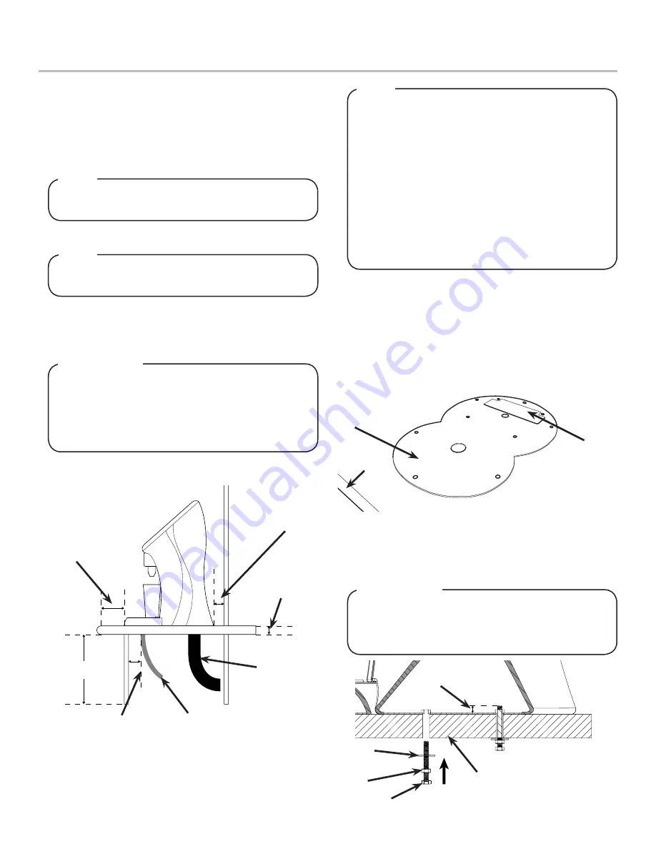
1. Select a location that is in close proximity to a properly
grounded electrical outlet, within 1.5 m (5 ft) of a drain, and
a water supply that meets the requirements shown in the
Specifications section found on page 2.
Min: 20 mm
Max: 225 mm
Min: 50 mm
Max: 42 mm
Max: 850 mm
A. Drain Tube
B. Inlet Tubes
A
B
To assure that beverage service is accessible to all
customers, Lancer recommends that counter height
and equipment selection be planned carefully. The
2010 ADA Standards for Accessible Design states that
the maximum reach height from the floor should be no
more than 1.2 meters (48 inches) if touch point is less
than 254 mm (10 inches) from the front of the counter,
or a maximum of 1.17 meters (46 inches) if the touch
point is more than 254 mm (10 inches) and less than
685 mm (27 inches) from the front of the counter. For
more information about the customer’s legal
requirements for the accessibility of installed
equipment, refer to 2010 ADA Standards for
Accessible Design - http://www.ada.gov.
NOTE
A. Mounting Plate
B. Counter Cutout
C. Counter Edge
A
B
C
2. Select a location that utilizes the clearances/space required
for installation.
The dispenser should only be installed in a location
where it can be overseen by trained personnel
NOTE
When attaching the tower to the mounting plate, make
sure the screws do not extend more than 20 mm (0.78
inches) from the top of the mounting plate. These could
damage the valves when installing the dispenser.
!
ATTENTION
E
A
B
C
A. Max. Height of 20 mm
B. Washer
C. Nut
D. Connecting Screw
E. Counter
D


