115
14
Appendix
14.1.7
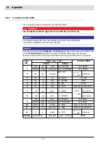
Connection Cable AK05
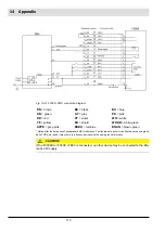
The connection cable is intended for use with the F300K.
DANGER!
The Connection Cable are approved for use with SELV or PELV only.
NOTICE
For special requirements it may be necessary to protect cable additionally.
The specific installation rules are to be observed.
NOTICE
Only the Connection Cable
AK05-51
is
UL Listed
approofed. For the use of the Flame scan-
ner as
UL Recognized
approofed, the other Connection Cable types can be used.
Devices shall be wired in accordance with NEC field wiring requirements for the location.
Plug
PIN
Cable - Core - Code
Function F300K
Farben
Zahlen
1
WH
ws
weiß
11
ELEVEN
Bus FSB-H
WHGN wsgn
weiß-grün
14
FOURTEEN Bus FSB-H
2
BK
sw
schwarz
10
TEN
Stand-by
3
RD
rt
rot
8
EIGHT
+ 24 VDC
4
BU
bl
blau
7
SEVEN
GND
5
PK
rs
rosa
6
SIX
+ 20 mA
6
GY
gr
grau
5
FIVE
Mode of operation BA-1
7
YE
ge
gelb
4
FOUR
Flame signal
8
GN
gn
grün
3
THREE
Flame signal
9
BN
br
braun
12
TWELVE
Bus FSB-L
BNGN brgn
braun-grün
13
THIRTEEN
Bus FSB-L
10
RDBU rtbl
rot-blau
9
NINE
Mode of operation BA-3
11
GYPK grrs
grau-rosa
1
ONE
Mode of operationBA-2
12
VT
vi
violett
2
TWO
Stand-by
Housing
Shield braid
weiß-gelb
gelb + schwarz
Shield
Summary of Contents for F300K Series
Page 2: ......
Page 26: ...25 5 User Interface 5 2 Menu tree ...
Page 31: ...30 6 Commissioning Marking information on the device Example F300K F300K UI FB30 Warning e g ...
Page 121: ...120 14 Appendix 14 3 EU Declaration of Conformity ...
Page 122: ...121 14 Appendix ...
Page 125: ...124 14 Appendix ...


